
Optical touch control screen based on optical gratings

An optical touch screen and grating technology, applied in the direction of optics, nonlinear optics, data processing input/output process, etc., can solve problems such as low resolution, affecting touch accuracy, affecting touch screen positioning performance, etc., to achieve improved color Purity, cost-saving effect

Active Publication Date: 2014-09-03
SHANGHAI JIAO TONG UNIV
View PDF6 Cites 21 Cited by
  • Summary
  • Abstract
  • Description
  • Claims
  • Application Information

AI Technical Summary

Problems solved by technology

In practical applications, if there is a problem with one or more infrared emitting tubes, it will affect the positioning performance of the touch screen
At the same time, the infrared emitting tube has an emitting angle, and the receiving tube has a wide range of receiving angles. If the surrounding reflection is to a certain extent, it will affect the touch accuracy and the resolution is low.

Method used


Image

  • Optical touch control screen based on optical gratings
  • Optical touch control screen based on optical gratings
  • Optical touch control screen based on optical gratings

Examples


Embodiment Construction

[0034] The present invention will be described in detail below in conjunction with the embodiments and accompanying drawings, but the protection scope of the present invention should not be limited thereby.

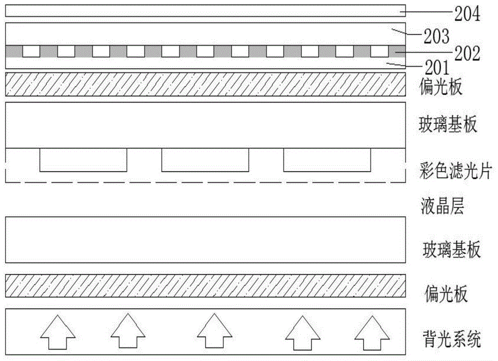
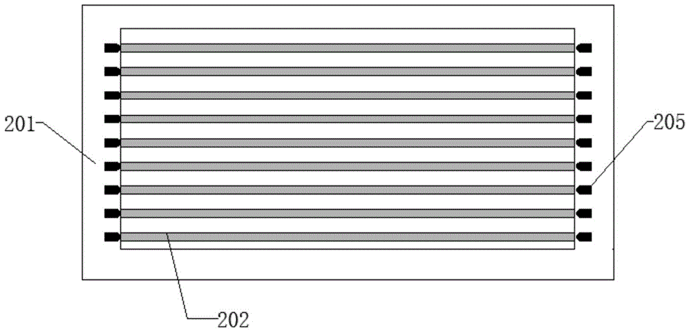
[0035] An optical touch screen based on a grating, including a substrate, a grating, an optical waveguide layer, a light receiver, and a transparent protective layer, which is characterized in that a transparent substrate, a grating, an optical waveguide, and a transparent protective layer are placed in sequence on a liquid crystal display system ,Such as figure 1 shown.

[0036] The grating can be embedded in the waveguide or the transparent substrate, or a separate layer can be located between the waveguide and the substrate. The grating can be of embossed or mosaic type.

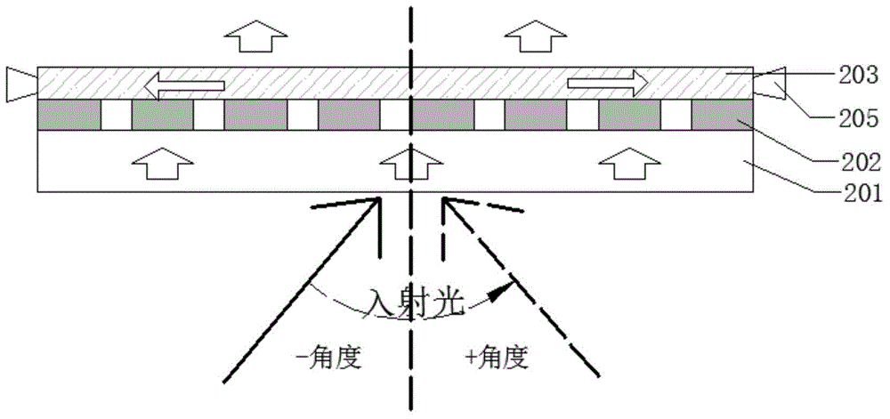
[0037] The optical receiver is installed on any at least two sides of the optical waveguide layer or directly above or below the optical waveguide layer, and the receiving surface of the receiver ...


PUM


Abstract

An optical touch control screen based on optical gratings comprises a glass substrate, the optical gratings, an optical waveguide layer, optical receivers and a transparent protective layer. On the basis of a liquid crystal display system, diffraction of the optical gratings is utilized, light with a specific wave length in display light penetrating through a color filter can become a waveguide mode which can be transmitted in waveguide and serves as detection light for touch control, and cycles of the optical gratings correspond to different sub-pixels in the filter in a one-to-one mode. A light source does not need to be additionally provided, cost is saved, and color purity of display light is effectively improved. Detection light is one of three-primary colors in pixels, and touch control precision is improved and can reach the level of pixels.

Description

technical field [0001] The invention relates to an interactive touch technology in the field of information display technology, in particular to a touch technology based on grating coupling and waveguide light transmission, which has a grating and a waveguide array, and the grating period corresponds to the pixel array of a display device. Background technique [0002] According to different technical principles, touch technology mainly has four variables: sound (surface acoustic wave technology), light (infrared technology, optical technology, holographic touch), electricity (resistive and capacitive), and pressure (vector pressure sensing technology). way of perception. According to the four variable sensing technologies of acousto-optic voltage, the mainstream touch screen products currently commercialized in the market are: (1) resistive touch screen; (2) capacitive touch screen; (3) surface acoustic wave touch screen; (4) infrared touch screen. [0003] The resistive t...

Claims


Application Information

Patent Timeline
Patent Type & Authority Applications(China)
IPC IPC(8): G06F3/042G02F1/1333
Inventor 叶志成崔杰洪芃力
Owner SHANGHAI JIAO TONG UNIV
Learn More