
CPU (Central Processing Unit) startup fault positioning system and positioning method thereof

A technology of fault location and location method, applied in the direction of detecting faulty computer hardware, etc., can solve the problems of damaged FLASH chip, low efficiency, fault location error, etc., to avoid the effect of signal measurement and judgment

Inactive Publication Date: 2014-09-03
PHICOMM (SHANGHAI) CO LTD
View PDF5 Cites 10 Cited by
  • Summary
  • Abstract
  • Description
  • Claims
  • Application Information

AI Technical Summary

Problems solved by technology

[0005] Although the existing fault priority elimination method can solve the problem of starting the CPU, the efficiency is very low, and it is not suitable for the rapid positioning of faulty chips when mass production is carried out.
In addition, the secondary soldering of FLASH may also damage the original non-faulty FLASH chip. If the secondary soldering is still unsuccessful, the fault may be wrongly located on the RAM chip.

Method used


Image

  • CPU (Central Processing Unit) startup fault positioning system and positioning method thereof
  • CPU (Central Processing Unit) startup fault positioning system and positioning method thereof
  • CPU (Central Processing Unit) startup fault positioning system and positioning method thereof

Examples


Embodiment Construction

[0034] The present invention will be further elaborated below by describing a preferred specific embodiment in detail in conjunction with the accompanying drawings.

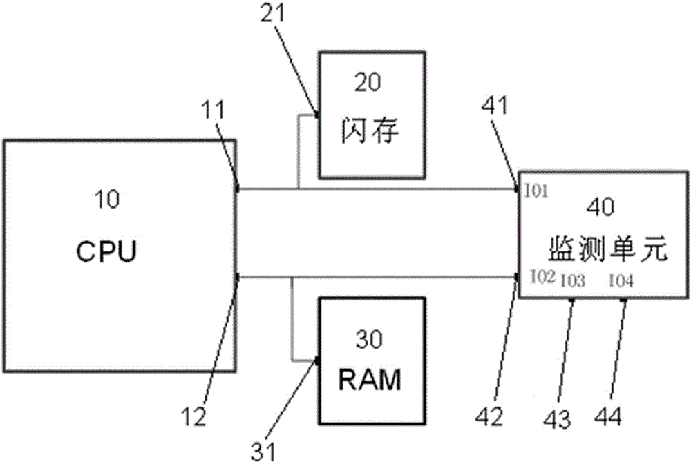
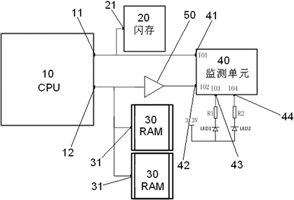
[0035] Such as figure 1 As shown, a CPU starts a fault location system, and the location system includes: a CPU 10 , a flash memory 20 , a RAM 30 and a monitoring unit 40 connected thereto. The flash memory signal monitoring end 41 of the monitoring unit 40 is respectively connected to the input end 21 of the flash memory 20 and the flash memory chip select signal output end 11 of the CPU 10 . The RAM signal monitoring terminal 42 of the monitoring unit 40 is respectively connected to the input terminal 31 of the RAM 30 and the RAM chip selection signal output terminal 12 of the CPU 10 . The monitoring unit 40 also includes a first status output indicating terminal 43 and a second status output indicating terminal 44, which respectively display the fault condition of the fault location system.

[0036] Such as ...


PUM


Abstract

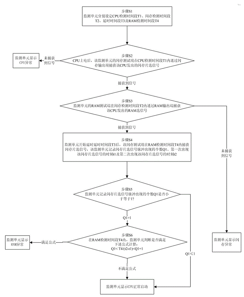
The invention discloses a CPU (Central Processing Unit) startup fault positioning system and a positioning method of the CPU startup fault positioning system. The positioning system comprises a CPU, and a flash memory, an RAM (Random Access Memory) and a monitoring unit which are connected with the CPU, wherein a flash memory signal monitoring end of the monitoring unit is respectively connected with the input end of the flash memory and a flash memory chip selection signal output end of the CPU; an RAM signal monitoring end of the monitoring unit is respectively connected with an RAM input end and an RAM chip selection signal output end of the CPU; the monitoring unit further comprises a first state output indication end and a second state output indication end which are used for respectively displaying a fault condition of the fault positioning system. In a CPU startup process, a FLASH chip selection signal is captured in the CPU startup process and an RAM chip selection signal is captured; the monitoring unit is used for judging whether the CPU can be normally started up or not and the reason of a CPU startup fault according to the captured FLASH chip selection signal and RAM chip selection signal. The positioning system can be used for rapidly and accurately positioning a hardware fault in the CPU startup process and avoids signal measurement and judgment by using various instruments and meters; the positioning system is applicable to startup fault positioning of electronic equipment in large-batch production.

Description

technical field [0001] The invention relates to a computer detection system and a detection method, in particular to a CPU startup fault location system and a location method thereof. Background technique [0002] With the continuous development of IC technology and electronic equipment, the volume of the CPU, the core part of electronic equipment, is constantly decreasing. The built-in ROM and RAM space of the CPU can no longer meet the application requirements of complex systems. It is necessary to have a larger storage space for storage. data and code. Therefore, external flash memory (FLASH for short) and RAM have become the main expansion methods of the CPU at present. [0003] In the existing CPU system, the CPU usually has FLASH and RAM memory attached to it. FLASH is used to store startup code, system image and other files, and RAM is used for data access during CPU operation. After the CPU is powered on, it may be due to poor welding. , chip damage, code error and...

Claims


Application Information

Patent Timeline
Patent Type & Authority Applications(China)
IPC IPC(8): G06F11/22
Inventor 高浩
Owner PHICOMM (SHANGHAI) CO LTD
Learn More