Method for controlling data transmission and DMA controller

A technology for controlling data and accessing controllers, which is applied in electrical digital data processing, instruments, etc., can solve the problems of system complexity, slow data speed, low transmission efficiency, etc., achieve simple system connection, reduce intermediate links, and fast transmission speed. Effect

Active Publication Date: 2014-09-03
DATANG MICROELECTRONICS TECH CO LTD
View PDF6 Cites 10 Cited by
  • Summary
  • Abstract
  • Description
  • Claims
  • Application Information

AI Technical Summary

Problems solved by technology

[0006] The existing design of the DMA controller has the technical disadvantages of frequent data conversion between memories with different data widths, low transmission efficiency, and long time consumption:
When transferring between memories or peripherals with different data widths, it is necessary to add data conversion or data cache design in the system or memory interface module, resulting in system complexity and slow data speed.
[0008] In addition, when the DMA controller of the existing design is working, it will occupy the system bus
At this time, the CPU cannot access other slave modules through the system bus, and can only operate after the DMA work is completed.
At this time, the CPU may not be able to process the interrupt signals of peripherals or other modules in time, which has certain limitations in system use.

Method used


Image

  • Method for controlling data transmission and DMA controller
  • Method for controlling data transmission and DMA controller
  • Method for controlling data transmission and DMA controller

Examples


Embodiment 1

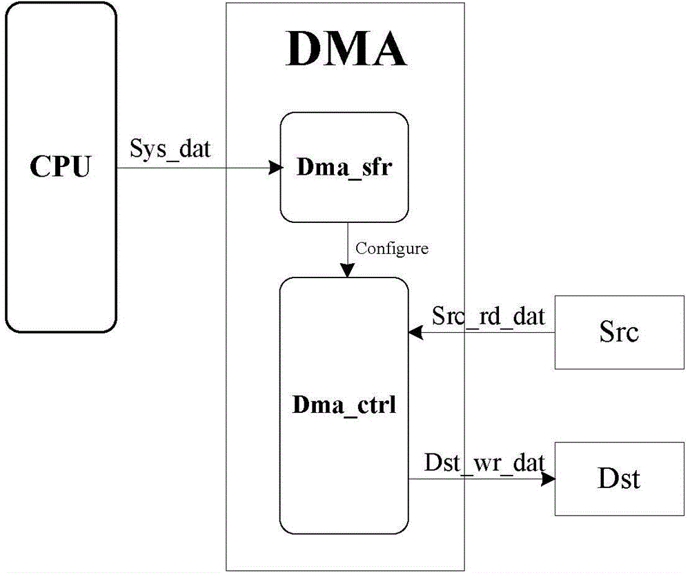
[0091] Figure 6 It is a simulation diagram of data width transmission of the embodiment of the present invention: 8—>8bits. Configuration information: source start address Dmac_src_addr=32'h1000, destination start address Dmac_dst_addr=32'h2000, transmission length Dmac_len="3" (indicating 4 times of transmission), transmission width conversion parameter Dmac_width="0" (indicating from source —>The destination width is 8—>8bits), when Dmac_en="1" is enabled, DMA starts to work.

[0092] The source address (Src_addr) starts from "1000", and when the read signal (Src_rd) and the read acknowledgment signal (rd_dack) are both "1", the data (Src_rd_data) "12" is read out. After the read operation, the destination address (Dst_addr) starts from "2000", and when the write read signal (Dst_wr) and the write correct response signal (wr_dack) are both "1", write data (Dst_wr_data) "12", and Src_addr, Dst_addr Increase, so far complete a read and write.

[0093] This read and write o...

Embodiment 2

[0096] Figure 7 It is a simulation diagram of data width transmission of the embodiment of the present invention: 16—>16 bits. Configuration information: Dmac_src_addr=32'h1000, Dmac_dst_addr=32'h2000, Dmac_len="3" (transfer 4 bytes), Dmac_width="5" (indicates that the width from source -> destination is 16 -> 16 bits), when enabled When Dmac_en="1", DMA starts to work.

[0097] Src_addr starts from "1000", and when both Src_rd and rd_dack are "1", Src_rd_data is "3412". After the read operation, Dst_addr starts from "2000", and when both Dst_wr and wr_dack are "1", the write data Dst_wr_data is "3412", and Src_addr and Dst_addr increase. At this point, a read and write is completed.

[0098] This read and write operations are performed twice, and 4 bytes are transferred. After the data transmission is completed, the end flag signal Dmac_end is set to "1", the enable signal Dmac_en is set to "0", and the DMA module is finished.

Embodiment 3

[0100] Figure 8 It is a simulation diagram of data width transmission of the embodiment of the present invention: 32—>32bits. Configuration information: Dmac_src_addr=32'h1000, Dmac_dst_addr=32'h2000, Dmac_len="3" (transfer 4 bytes), Dmac_width="a" (indicates that the width from source -> destination is 32 -> 32 bits), when enabled When Dmac_en="1", DMA starts to work.

[0101] Src_addr starts from "1000", and when both Src_rd and rd_dack are "1", Src_rd_data is "7856_3412". After the read operation, Dst_addr starts from "2000", and when both Dst_wr and wr_dack are "1", the write data Dst_wr_data is "7856_3412", and Src_addr and Dst_addr increase. At this point, a read and write is completed.

[0102] This read and write operation is 1 time, and 4 bytes are transferred. After the data transmission is completed, the end flag signal Dmac_end is set to "1", the enable signal Dmac_en is set to "0", and the DMA module is finished.


PUM


Abstract

The invention provides a method for controlling data transmission and a DMA controller. The method comprises the steps that configuration information of a CPU is received and analyzed, wherein the configuration information includes transmission width conversion parameters; data are read from a source peripheral and converted into the corresponding data width to be written in a target peripheral according to the transmission width conversion parameters. The transmission mode adopted for the DMA controller acts on direct exchange data between memories, between the memories and the peripherals and between the peripherals, CPU read-write commands are not executed, a CPU cache does not need to be used, and therefore intermediate links are reduced; only the DMA controller needs to be configured, all read-write time sequences are executed by hardware, and therefore the rate of data transmission is greatly increased.

Description

technical field [0001] The invention relates to the field of integrated circuits, in particular to a method for controlling data transmission and a DMA (Direct Memory Access, memory direct access) controller. Background technique [0002] With the rapid development of the Internet and electronic products, application software containing a large amount of data such as audio and video tests the data processing capabilities of hardware chips, and the rapid transmission of large amounts of data has become an important performance indicator of today's chips. [0003] Compared with the CPU direct data transmission method, query method and interrupt method in the traditional system, the transmission method adopted by the DMA controller is to directly exchange data between memories, between memory and peripherals, and between peripherals and peripherals. . Does not execute CPU read and write instructions, and does not need to go through CPU cache, reducing intermediate links. As l...

Claims


Application Information

Patent Timeline
IPC IPC(8): G06F13/28
Inventor 王震
Owner DATANG MICROELECTRONICS TECH CO LTD
Why Eureka
Try Eureka