Multi-band MIMO antenna used for intelligent machine

A multi-band, smart phone technology, applied in antennas, antenna coupling, antenna grounding devices, etc., can solve the problems of inability to use MIMO antenna technology, the decoupling method cannot meet the requirements, and the design of MIMO antennas is difficult. High isolation, the effect of improving isolation

Inactive Publication Date: 2014-09-03
UNIV OF ELECTRONICS SCI & TECH OF CHINA
View PDF4 Cites 26 Cited by
  • Summary
  • Abstract
  • Description
  • Claims
  • Application Information

AI Technical Summary

Problems solved by technology

[0003] At present, the problem existing in the MIMO antenna system used in the smart machine is: how to realize the miniaturized, multi-band, high-isolation smart machine MIMO antenna in the complex smart machine environment
Due to the increasing metallization degree of smartphones and the reduction of antenna clearance area, the design of MIMO antennas for multi-band smartphones becomes more difficult. Moreover, with the reduction of antenna design space, the mutual coupling between MIMO antennas becomes The fatal problem is that the strong mutual coupling between MIMO antenna elements will reduce the radiation efficiency of the antenna and cannot take advantage of the advantages of MIMO antenna technology. However, when the distance between MIMO antenna elements is small, the isolation between antennas will become very strong.
In the current MIMO antenna decoupling methods, most of the decoupling methods are only suitable for narrow-band or high-band decoupling, and in the actual smart machine MIMO system needs to be compatible with the low-frequency mode, so most of the decoupling methods cannot meet the requirements of

Method used


Image

  • Multi-band MIMO antenna used for intelligent machine
  • Multi-band MIMO antenna used for intelligent machine

Examples


Embodiment Construction

[0019] The specific embodiments of the present invention will be further described below in conjunction with the accompanying drawings.

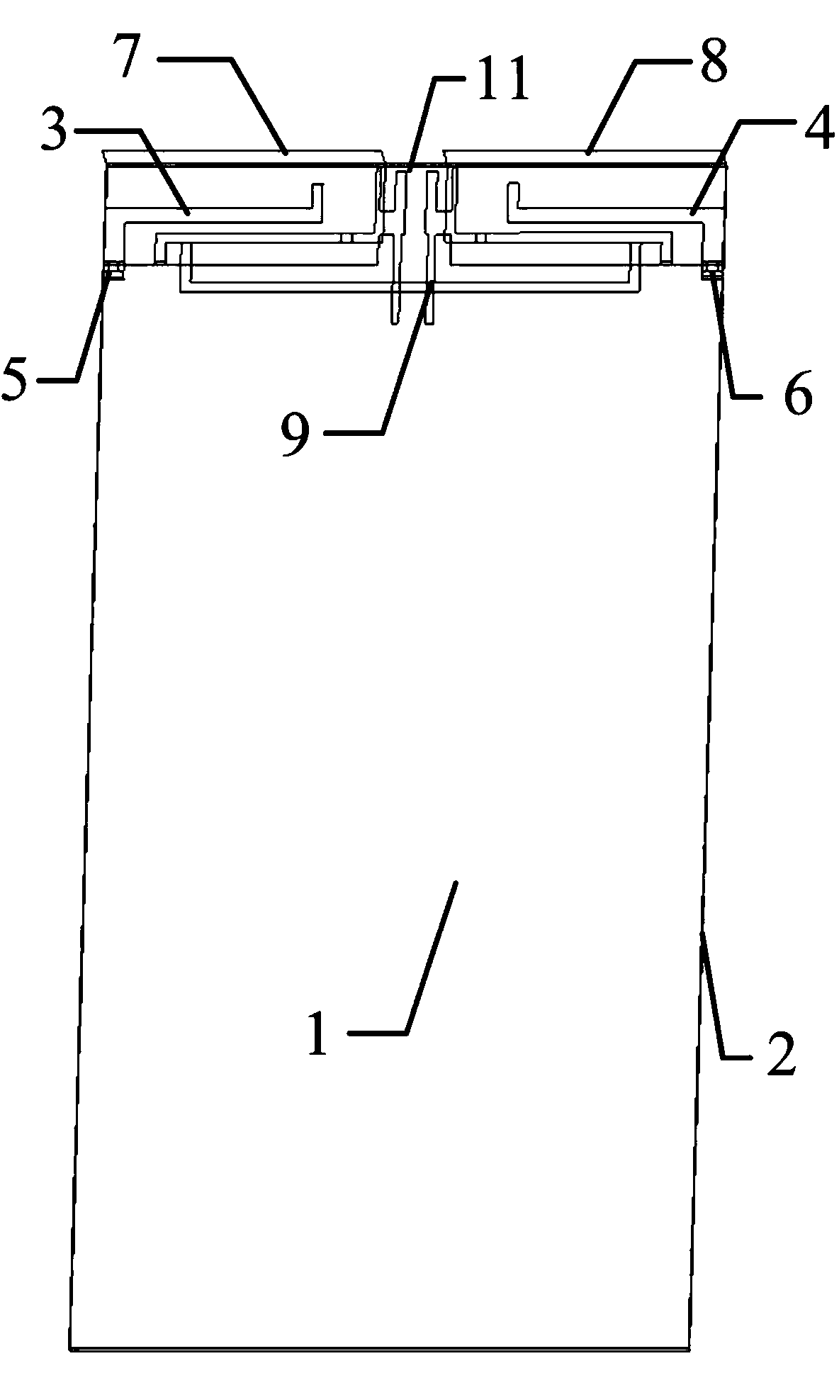
[0020] Such as figure 1 As shown, the multi-band MIMO antenna for smart phones includes a dielectric substrate 1, the back of the dielectric substrate 1 is provided with a floor 2 and a decoupling structure, the floor 2 and the decoupling structure are connected together, and the dielectric substrate 1 is provided with a first radiating unit 3, a second radiating unit 4, a first matching circuit 5, a second matching circuit 6, a first parasitic unit 7, a second parasitic unit 8, and a neutral line 9. The first The radiation unit 3 and the second radiation unit 4 have the same structure and are arranged symmetrically along the midline of the dielectric substrate 1, the parameters of the first matching circuit 5 and the second matching circuit 6 are the same, and the first matching circuit 5 is arranged on the first radiation In the unit 3, t...


PUM


Abstract

The invention discloses a multi-band MIMO antenna used for an intelligent machine. The antenna can achieve miniaturization, has multiple bands and is high in isolation. The antenna comprises a dielectric substrate, the back side of the dielectric substrate is provided with a floor and a decoupling structure, the floor and the decoupling structure are connected as a whole, and the front side of the dielectric substrate is provided with a first radiation unit, a second radiation unit, a first matching circuit, a second matching circuit, a first parasitic element, a second parasitic element and a neutral line. By means of a coupled feeding structure, the decoupling structure and matching circuit structures, miniaturization and broadband coverage of the antenna are achieved, so that double resonance of the antenna at a low frequency band is achieved, the GSM850 / 900 frequency band is successfully covered, the GSM1800 / 1900 / UMTS2100 / LTE2300 / 2500 frequency bands are covered at a high frequency band, the requirements for miniaturization and multi-band of the MIMO antenna of the intelligent machine are met, and high isolation between antenna units can be obtained by means of the neutral line. The antenna is suitable for being used and popularized in the field of terminal antennas.

Description

technical field [0001] The invention relates to the technical field of terminal antennas, in particular to a multi-band MIMO antenna for smart phones. Background technique [0002] With the advent of the 4G era, high-speed wireless data connections have become the development trend of mobile communications, and MIMO antenna technology, as a key technology of LTE, is an important means to improve data transmission rates and enhance the reliability of wireless connections. The data transmission method of smart phones mainly relies on wireless access. Therefore, MIMO antenna technology is widely used in smart phones, and the design of MIMO antenna system directly determines the communication performance of smart phones. [0003] At present, the problem existing in the MIMO antenna system used in the smart machine is: how to realize the miniaturized, multi-band, high-isolation smart machine MIMO antenna in the complex smart machine environment. Due to the increasing metallizati...

Claims


Application Information

Patent Timeline
Patent Type & Authority Applications(China)
IPC IPC(8): H01Q1/52H01Q1/48H01Q23/00
Inventor 陈忠祥李鹏鹏张李弯强云飞刘曦阳班永灵
Owner UNIV OF ELECTRONICS SCI & TECH OF CHINA
Why Eureka
Try Eureka