Input zero-ripple wave converter

A converter and ripple technology, applied in the field of input zero-ripple converters, can solve problems such as low efficiency, complex circuits, and difficult debugging

Active Publication Date: 2014-09-03
缪恢宏
View PDF7 Cites 8 Cited by
  • Summary
  • Abstract
  • Description
  • Claims
  • Application Information

AI Technical Summary

Problems solved by technology

The boost converter is mainly used to improve the power factor of the power supply. Since the Boost converter can only boost the voltage, in recent years, SEPIC converters have also been used. Since the second inductance of the SEPIC converter can be replaced by a transformer, the SE

Method used


Image

  • Input zero-ripple wave converter
  • Input zero-ripple wave converter
  • Input zero-ripple wave converter

Examples


Embodiment Construction

[0024] The present invention will be further described below in conjunction with the accompanying drawings.

[0025] (1) For DC power supply, frequency modulation-push-pull-BOOST converter

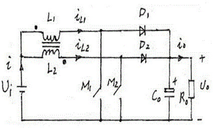
[0026] Such as figure 1 As shown, when the DC power supply is used, the circuit configuration of the frequency modulation-push-pull-BOOST converter is: DC power supply U i The positive pole comes out and is divided into two paths, which are respectively connected to the inductor L 1 and inductance L 2 , inductance L 1 and inductance L 2 coupled on an iron core, the inductance L 1 current i L1 and inductance L 2 current i L2 Inflow from the opposite end. Inductance L 1 The outlet all the way through the switch tube M 1 Back to Power U i Negative pole, all the way through diode D1 to capacitor C 0 and load R 0 power supply; inductance L 2 The outlet all the way through the switch tube M 2 Back to Power U i Negative pole, all the way through diode D 2 To the capacitor C 0 ...


PUM


Abstract

The invention relates to an input zero-ripple wave converter. The input zero-ripple wave converter is characterized in that two same BOOST converters are connected in parallel, or two same SEPICs are connected in parallel, trigger circuits of the two BOOST converters or the two SEPICs are in a push-pull-trigger state, input delta current waveforms of the two converters are differed in a half cycle on time, and thus, the currents supplied by a direct-current power supply are ripple-wave-free constant direct currents; if a supplying power supply is a sinusoidal alternating current power supply, the supplied current is an alternating current in same frequency and phase with the voltage of the alternating current power supply. The input zero-ripple wave converter is mainly applied to a switch power supply and can be applied to centralized electronic ballasts (each can be connected with dozens or hundreds of fluorescent lamps or electronic energy-saving lamps) so as to realize the following effects: the power factor is increased, the efficiency is increased, ripple waves at an input ends are eliminated, the manufacturing cost is lowered, the energy is saved, and the environment is protected; the input zero-ripple wave converter can be further applied to direct current voltage regulation and frequency conversion techniques.

Description

Technical field [0001] The invention belongs to an input zero-ripple converter. The input zero-ripple converter includes a frequency modulation-push-pull-Boost converter and a frequency modulation-push-pull-SEPIC converter. It is mainly used in switching power supplies, and can also be used in centralized electronic ballasts (one centralized electronic ballast can be connected to dozens or hundreds of fluorescent lamps or electronic energy-saving lamps). Both improve power factor, increase efficiency, and eliminate ripple at the input. Can reduce the cost, energy saving and environmental protection. In addition, it can also be used in DC voltage regulation and frequency conversion technology. Background technique [0002] The power supply technology includes converting the AC power provided by the grid into a primary DC power supply (AC / DC conversion), the secondary DC power supply in the DC form (DC / DC conversion), and converting the AC power of the grid into various freq...

Claims


Application Information

Patent Timeline
IPC IPC(8): H02M1/12H02M1/14
Inventor 缪恢宏缪吉
Owner 缪恢宏
Why Eureka
Try Eureka