An associated gas condensate recovery device

A technology of recovery device and associated gas, which can be used in combined devices, gas fuel, petroleum industry, etc., and can solve problems such as incomplete gas-liquid separation

Active Publication Date: 2016-04-20
XIAN CHANGQING TECH ENG
View PDF5 Cites 1 Cited by
  • Summary
  • Abstract
  • Description
  • Claims
  • Application Information

AI Technical Summary

Problems solved by technology

[0004] The purpose of the present invention is to overcome the problem of incomplete gas-liquid separation in existing associated gas condensate recovery devices

Method used


Image

  • An associated gas condensate recovery device
  • An associated gas condensate recovery device
  • An associated gas condensate recovery device

Examples


Embodiment 1

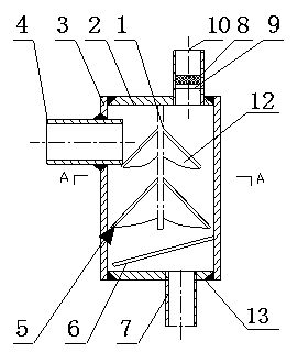
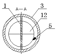
[0022] In order to overcome the defect of incomplete gas-liquid separation in the existing associated gas condensate recovery device, this embodiment provides a figure 1 , 2 The associated gas condensate recovery mechanism shown includes a cylinder body 3, an upper end cap 2 welded to the upper end surface of the cylinder body 3 and a lower end cap 13 welded to the upper end surface of the cylinder body 3, and a lower end cap 13 welded to the upper part of the outer wall of the cylinder body 3 and penetrating through the transverse direction of the cylinder body 3. The air inlet pipe 4, the longitudinal air outlet pipe 10 arranged on the upper end head 2 away from the horizontal air inlet pipe 4 and passing through the upper end head 2, the longitudinal liquid discharge pipe 7 arranged at the bottom of the lower end head 13 and the branch pipe arranged in the cylinder body 3 Liquid plate 5. A vertical baffle 1 extending longitudinally downward is provided on the inner surface...

Embodiment 2

[0024] On the basis of Embodiment 1, this embodiment provides such as figure 1 , 2 The liquid separator 5 on the same surface of the baffle plate 1 shown in .3 is composed of at least two fan-shaped steel plates 12, and the angle between the two planes of the two fan-shaped steel plates 12 is greater than zero and less than 180 degrees. The multi-layer inclined liquid separator 5 can ensure that the associated gas undergoes multiple collisions in the cylinder 3, thereby separating more liquid carried in the gas. The inclined design ensures that the separated liquid flows down smoothly, avoiding the Retention of fluid on the surface causes secondary entrainment of gas. Production practice has proved that when the angle between the fan-shaped steel plate 12 and the baffle plate is 45° and the angle between the bottom surfaces of the two fan-shaped steel plates 12 is 120°, the best liquid separation effect can be achieved.

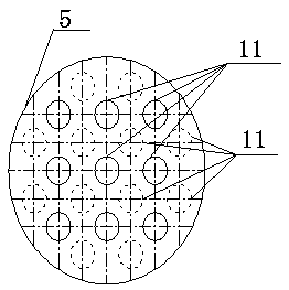
[0025] The radius of the multi-stage liquid separator...

Embodiment 3

[0030] On the basis of Embodiment 1, this embodiment provides such as Figure 4 The single liquid separator plate 5 on the same side of the baffle plate 1 shown is made of a steel plate formed by hot simmering, and the liquid separator plate 5 is provided with a raised edge 16 intersecting with the baffle plate, and the raised edge 16 will separate the liquid The plate 5 is divided into a first liquid separation plate 14 and a second liquid separation plate 15 with the raised edge 16 as the axis of symmetry, and the angle between the first liquid separation plate 14 and the second liquid separation plate 15 is greater than zero and less than 180 degrees . Production practice has proved that when the angle between the separator plate 5 and the baffle is 45° and the angle between the first separator plate 14 and the second separator plate 15 is 120°, the best liquid separation effect can be achieved.

[0031] The positional relationship of up, down, left and right mentioned abo...


PUM

PropertyMeasurementUnit
angleaaaaaaaaaa

Abstract

The invention provides an associated gas condensate recovery device which comprises a cylinder body, an upper end seal head welded on the upper end surface of the cylinder body, a lower end seal head welded on the lower end surface of the cylinder body, a transverse gas inlet pipe welded on the upper part of the outer wall of the cylinder body and penetrating the cylinder body, a longitudinal gas outlet pipe arranged on the upper end seal head and far away from the horizontal gas inlet pipe and penetrating the upper end seal head, a longitudinal draining pipe arranged on the bottom of the lower end seal head, and liquid dividing plates arranged in the cylinder body; the inner surface of the upper end seal head is provided with a vertical-direction baffle plate extending downwards along the longitudinal direction; multiple liquid dividing plates are successively arranged on the left side and the right side of the baffle plate from top to bottom and are inclined downwards; gaps are formed between the liquid dividing plates and the bottom of the cylinder body. Therefore, the device can greatly improve the gas-liquid separation rate of associated gas, and ensures the associated gas is not carried with liquids when entering a burner and can be fully burnt.

Description

technical field [0001] The invention relates to a device for recovering associated gas condensate, specifically belonging to the field of petroleum gathering and transportation. Background technique [0002] Associated gas refers to the gas that escapes with the oil in the oil reservoir and the natural gas partially dissolved in the oil. Associated gas contains more methane, ethane, etc., which can be used for heating of oil gathering pipelines, fuel gas of water jacket heating furnace, etc. At present, heating, buffering and separation are usually integrated into a set of equipment during crude oil gathering and transportation, and the separated associated gas is directly burned as fuel gas for the heating furnace after gas-liquid separation. [0003] Before the associated gas enters the burner, gas-liquid separation is required to separate the residual liquid (free water or light oil, etc.) in the associated gas, so as to ensure that the associated gas has no liquid entra...

Claims


Application Information

Patent Timeline
Patent Type & Authority Patents(China)
IPC IPC(8): B01D45/08B01D50/00C10L3/10
Inventor 朱小军徐东武文华雷学锋任鹏辉李超解奋
Owner XIAN CHANGQING TECH ENG
Why Eureka
Try Eureka