
A machining center processing standard base plate

A machining center and standard technology, applied in metal processing equipment, metal processing mechanical parts, manufacturing tools, etc., can solve problems such as affecting the layout and working environment of the processing site, complicated debugging, and complicated installation, so as to reduce the time for replacing fixtures and fixtures. Accurate work and convenient replacement of fixtures

Active Publication Date: 2015-09-09
NINGBO XUSHENG AUTO TECH CO LTD
View PDF4 Cites 0 Cited by
  • Summary
  • Abstract
  • Description
  • Claims
  • Application Information

AI Technical Summary

Problems solved by technology

There is a 0 point on the machine tool, and each time it is replaced, the fixture must be aligned according to the reference and parallel lines so that it completely matches the measured 0 position, and then all hydraulic oil pipes are connected from the outside, and then debugging is basically time-consuming one day
It is difficult to measure the 0 point, difficult to control the position of the fixture and the parallel line, the debugging is complicated, the specifications of the fixture are different, the installation is complicated, and the efficiency is low
The external connection of the hydraulic oil circuit is relatively messy, which affects the layout of the processing site and the working environment

Method used


Image

  • A machining center processing standard base plate
  • A machining center processing standard base plate

Examples


Embodiment Construction

[0013] The present invention will be further described below in conjunction with the accompanying drawings and embodiments.

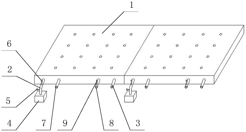
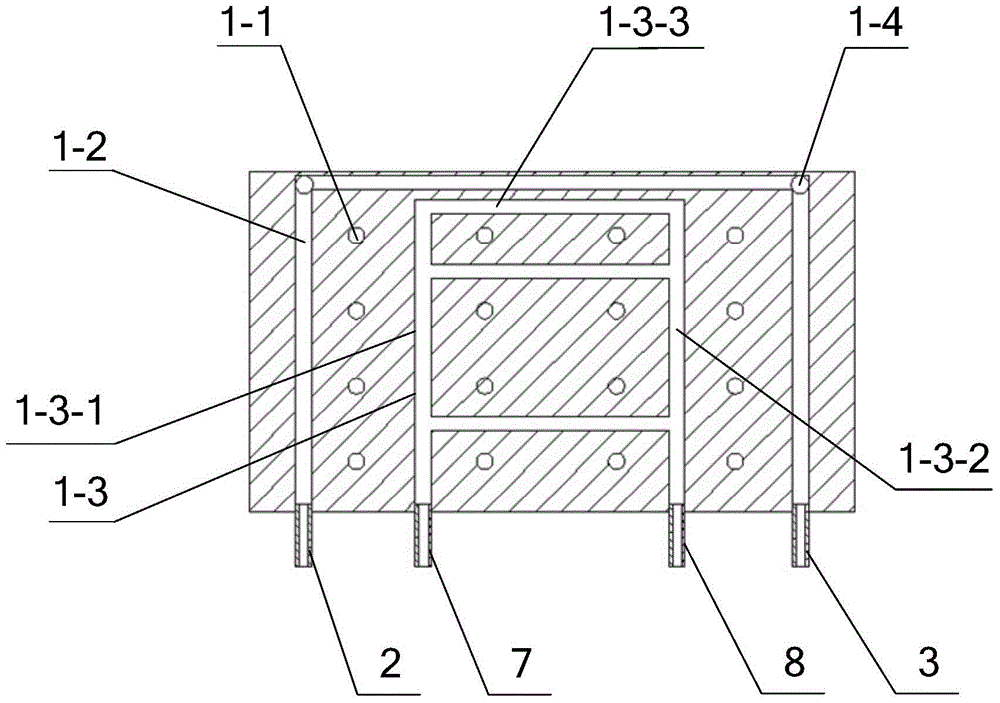
[0014] like figure 1 and 2 As shown, a processing standard base plate of a machining center includes two standard base plate assemblies with fixed end faces; the standard base plate assembly includes a standard base plate 1, a hydraulic oil input pipe 2, a hydraulic oil discharge pipe 3, a hydraulic oil switch 5, and a cooling water input pipe 7 and cooling water discharge pipe 8; the standard bottom plate 1 is provided with sixteen positioning pin holes 1-1 in a rectangular array along the vertical direction, and each row and column includes four positioning pin holes 1-1; two standard The hole diameter and hole spacing of the positioning pin holes 1-1 of the bottom plate assembly are respectively matched with one kind of fixture. When installing, the two fixtures can be matched with the measured 0 position on the machine tool, no debugging is require...


PUM


Abstract

The invention discloses a standard processing bottom plate of a processing center, and aims at solving the problems of the existing processing center that time is cost for debugging during replacing a clamp, and the external connection of a hydraulic oil channel influences the working environment. The standard processing bottom plate of the processing center comprises a plurality of standard bottom plate assemblies; each standard bottom plate assembly comprises a standard bottom plate, a hydraulic oil input pipe, a hydraulic oil receiving and discharging pipe, a hydraulic oil switch, a cooling water input pipe and a cooling water draining pipe; a plurality of positioning pin holes which are arranged as a rectangular array are upright formed in the standard bottom plates; a hydraulic oil pipeline and a cooling water pipeline are formed at the same level in each standard bottom plate; an input of each hydraulic oil pipeline is communicated with a pressure vessel through each hydraulic oil input pipe, and while an output of each hydraulic oil pipeline is connected with each hydraulic oil receiving and discharging pipe; a hydraulic oil switch and a pressure gage are arranged on each hydraulic oil input pipe; the input of each cooling water pipeline is connected with each cooling water input pipe, and while the output of each cooling water pipeline is connected with each cooling water draining pipe; a water temperature gage is arranged on each cooling water draining pipe. According to the standard processing bottom plate of the processing center, each standard bottom plate assembly is matched with a clamp, any debugging is not performed, and the clamp can be replaced conveniently.

Description

technical field [0001] The invention belongs to the field of processing equipment, and in particular relates to a processing standard bottom plate of a processing center. Background technique [0002] In the existing machining center, a specific fixture is used for a certain product during machine tool processing, and the fixture is replaced at the same time when the processed product is replaced. There is a 0 point on the machine tool, and each time it is replaced, the fixture must be aligned according to the reference and parallel lines so that it completely matches the measured 0 position, and then all hydraulic oil pipes are connected from the outside, and then debugging is basically time-consuming one day. It is difficult to measure the 0 point, it is difficult to control the position of the fixture and the parallel line, the debugging is complicated, the specifications of the fixture are different, the installation is complicated, and the efficiency is low. The exter...

Claims


Application Information

Patent Timeline
Patent Type & Authority Patents(China)
IPC IPC(8): B23Q3/00
CPCB23Q3/10B23Q11/12
Inventor 林国峰曾韦徐曦东
Owner NINGBO XUSHENG AUTO TECH CO LTD
Learn More