Abrasive belt cutting structure

An abrasive belt and center shaft technology, applied in the field of vertical abrasive belt slitting machines, can solve the problems of prolonged non-working time, troublesome next process, low stability of the slitting machine, etc., so as to reduce rotation and tool movement. Influence, ensure work stability, and shorten the effect of non-working time

Inactive Publication Date: 2014-09-10
CHENGDU HAILINGDA MACHINERY
View PDF10 Cites 0 Cited by
  • Summary
  • Abstract
  • Description
  • Claims
  • Application Information

AI Technical Summary

Problems solved by technology

The stability of the traditional slitting machine is low, especially in the long-term use process. The decrease in the stability of the whole machine will not only affect the working efficiency of the slitting machine, but also affect the product quality, and will also affect the next process. cause trouble and unnecessary waste
When the tool divides the abrasive belt, due to the high hardness of the sand grains on the abrasive belt, they will wear each other when the tool and the abrasive belt interact, and when the width of the abrasive belt to be cut is different, the tool needs to be replaced, which greatly prolongs the It shortens the non-working time, and also leads to a great reduction in the practicability of the slitting machine

Method used


Image

  • Abrasive belt cutting structure
  • Abrasive belt cutting structure

Examples


Embodiment 1

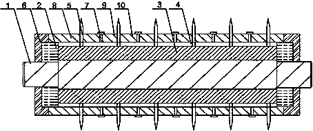
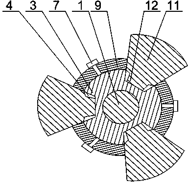
[0022] Such as figure 1 with figure 2 As shown, the abrasive belt cutting structure 5 of the present invention includes a central shaft 1, and the two ends of the central shaft 1 are rotated and arranged on the bearing seat 2. There are a plurality of trapezoidal grooves 4 distributed in an annular array, the trapezoidal grooves 4 are coaxial with the central axis 1, and also include a plurality of knives 5 and fixed blocks 8, the fixed blocks 8 are installed at both ends of the tool shaft 3, The cutter 5 is slidingly arranged in the trapezoidal groove 4, and the bottom end of the cutter 5 cooperates with the trapezoidal groove 4, and a spacer is installed between two adjacent cutters 5, and a threaded blind hole is provided on the cutter shaft 3, and the spacer The sleeve is fixed on the tool shaft 3 through the threaded blind hole through the bolt 7, and the two ends of the spacer are in contact with the end face of the cutter 5. When the present invention works, the cent...

Embodiment 2

[0024] Such as figure 2 As shown, in this embodiment, on the basis of Embodiment 1, the cutter 5 includes an arc-shaped cutter head 11 and a support portion 12 connected to each other, the support portion 12 is trapezoidal, and the support portion 12 cooperates with the trapezoidal groove 4 . The arc-shaped cutter head 11 can ensure a longer contact time with the abrasive belt during cutting, and the trapezoidal support part 12 cooperates with the trapezoidal groove 4, so that the tool 5 is stressed during high-speed rotation and in contact with the abrasive belt. It has strong stability during operation, and avoids the quality reduction of the cutting abrasive belt caused by the loosening of the cutter 5 during work.

Embodiment 3

[0026] Such as figure 1 As shown, on the basis of Embodiment 1, the present embodiment includes the spacer A9 arranged at intervals and the spacer B10 matched with the spacer A9, and the spacer A9 and the spacer B10 are respectively fixed during operation. On both sides of the cutter 5. When the required width of the cut strips is the same, the spacer A9 is the same as the spacer B10 to ensure that the distance between the blades is equal; when the width of the spacer A9 is smaller than the spacer B10, the adjacent two knives 5 The distances between them are not equal, and the widths of the sand strips obtained after cutting the abrasive belts are also not the same, ensuring that the present invention can produce sand strips of different widths without changing the cutter 5, greatly increasing its applicability. scope.


PUM


Abstract

The invention discloses an abrasive belt cutting structure which comprises a center shaft. The two ends of the center shaft are rotatably arranged on bearing pedestals, a tool mounting shaft is arranged on the center shaft in a sleeved mode, a plurality of dovetail grooves distributed in an annular array mode are formed in the tool mounting shaft, and the dovetail grooves and the center shaft are coaxial. A plurality of tools and fixed blocks are further included, the fixed blocks are arranged at the two ends of the tool mounting shaft, the tools are arranged in the dovetail grooves in a sliding mode, the bottom ends of the tools are matched with the dovetail grooves, a separation sleeve is arranged between two adjacent tools, threaded blind holes are formed in the tool mounting shaft, the separation sleeves are fixedly arranged on the tool mounting shaft with bolts penetrating through the threaded blind holes, and two ends of the separation sleeves are in contact with the end faces of the tools. When the sizes of the separation sleeves on two sides of the tools are equal, the distances between the adjacent tools are equal. When the sizes of the separation sleeves on two sides of the tools are different, the distances between the adjacent tools are different, abrasive strips of various widths are produced when abrasive belts are cut, the tools are prevented from being frequently replaced in the machining process, the nonworking time is shortened, and the practicality of the structure is improved.

Description

technical field [0001] The invention relates to a vertical abrasive belt slitting machine, in particular to an abrasive belt cutting structure. Background technique [0002] The slitting machine is a kind of equipment for longitudinally cutting wide roll materials. According to its scope of use, it can be divided into the following categories: for slitting paper, which is also the mainstream product in packaging equipment at present, and it is often seen in the packaging market; for Slitting industries such as leather, cloth, plastic, film, etc.; used for slitting metal coils, such as slitting strip steel, stainless steel, copper, etc., which are mainly used for steel processing plants to determine steel market operators, Steel rolling mills, electrical appliances, automobiles, stamping parts, etc. [0003] The working efficiency of the slitting machine is related to the following factors: slitting speed, yield, non-running time, stability, etc. The slitting speed is an im...

Claims


Application Information

Patent Timeline
Patent Type & Authority Applications(China)
IPC IPC(8): B26D1/28B26D7/26
Inventor 陈志强
Owner CHENGDU HAILINGDA MACHINERY
Why Eureka
Try Eureka