
Novel laser marking system

A new type of laser marking technology, applied in laser welding equipment, printing, auxiliary devices, etc., can solve the problems of high price and high price of light control and intelligent central control system, achieve the effect of simplifying structure and reducing manufacturing cost

Active Publication Date: 2014-09-10
NANTONG MEELAIN ELECTRIC APPLIANCE CO LTD
View PDF4 Cites 0 Cited by
  • Summary
  • Abstract
  • Description
  • Claims
  • Application Information

AI Technical Summary

Problems solved by technology

[0003]The traditional laser marking machine is relatively expensive due to the high price of light control and intelligent central control system, which is the main factor affecting its promotion and use. Therefore, there is an urgent need for a laser marking system with a lower price in the market.

Method used


Image

  • Novel laser marking system
  • Novel laser marking system
  • Novel laser marking system

Examples


Embodiment 1)

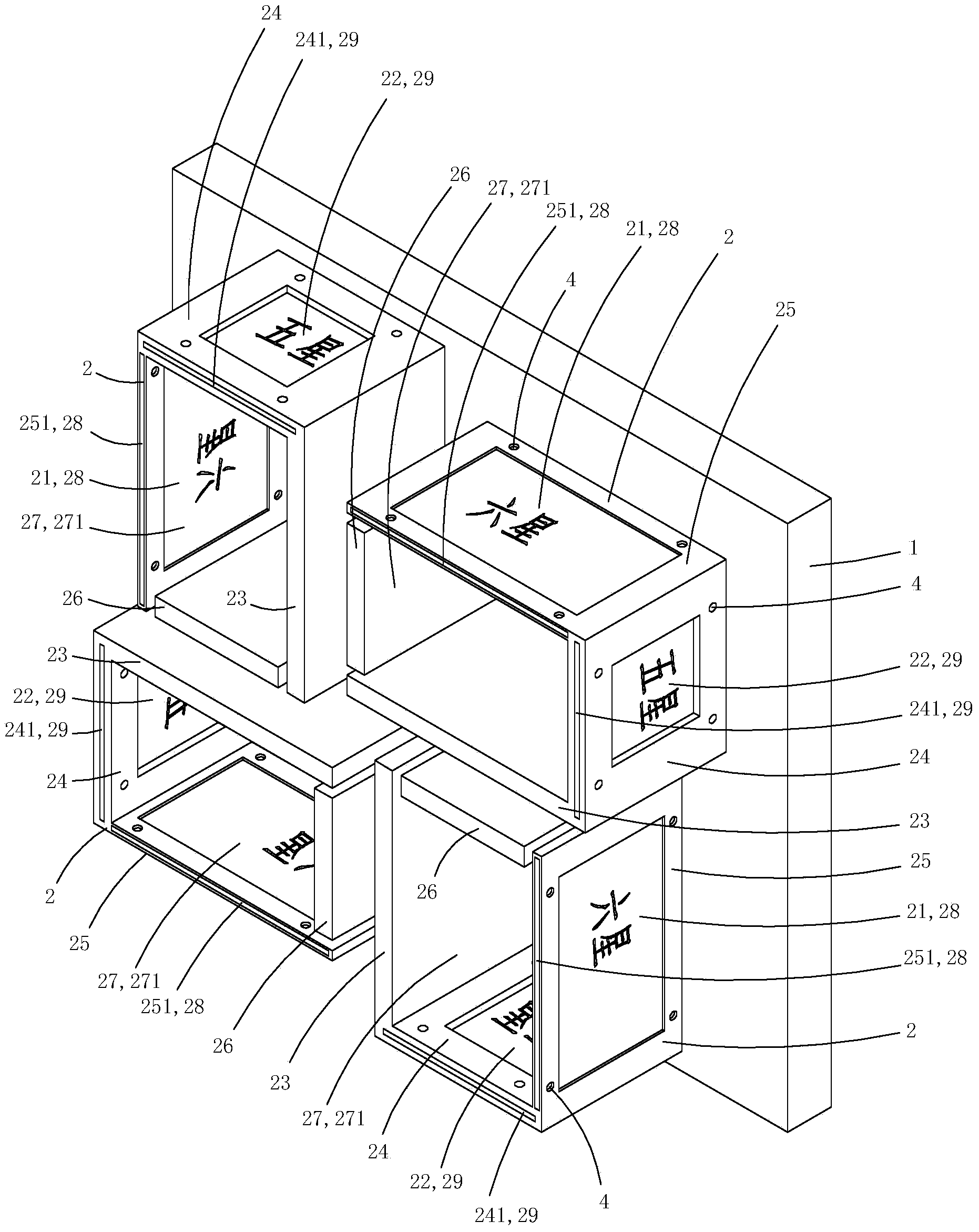
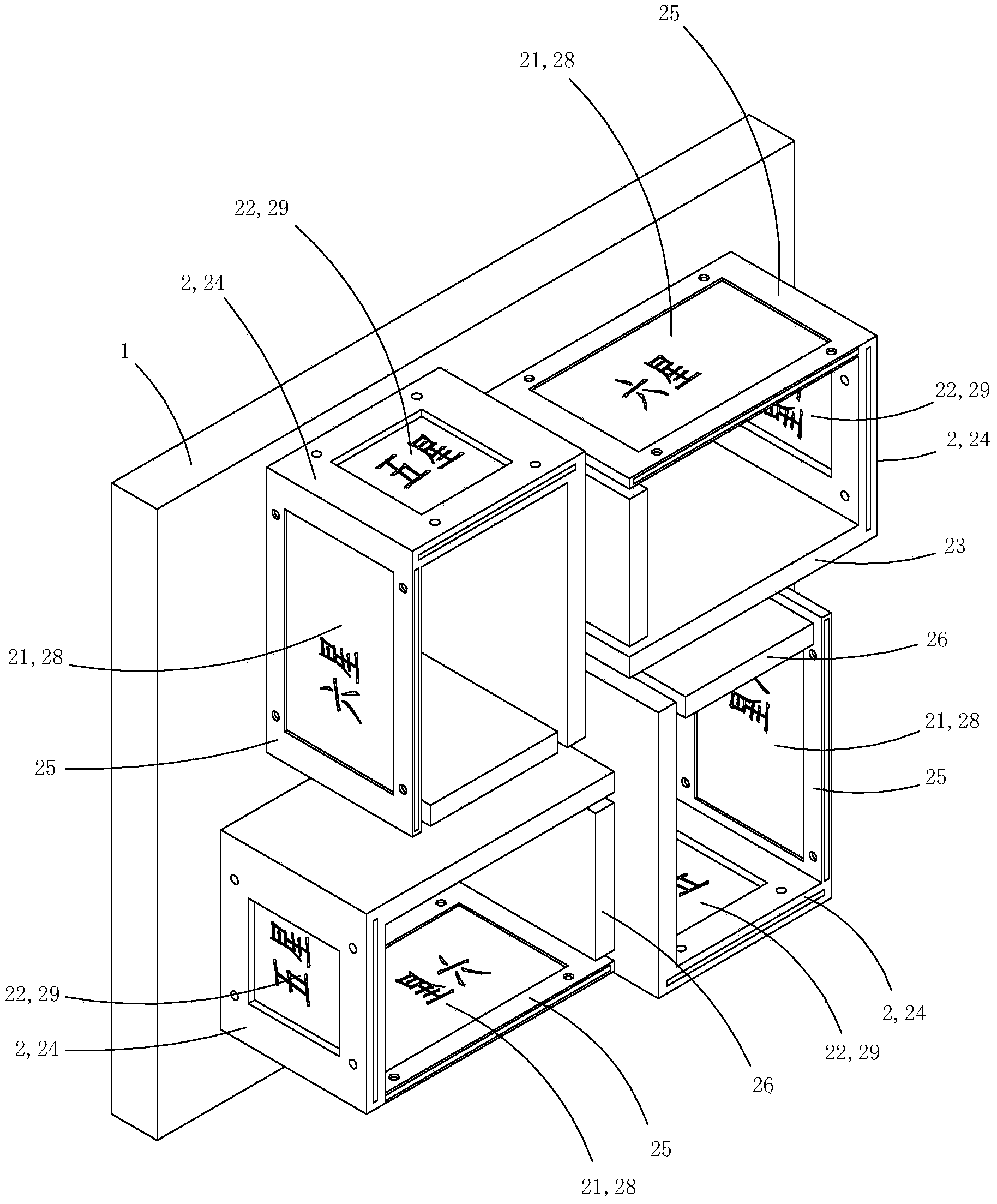
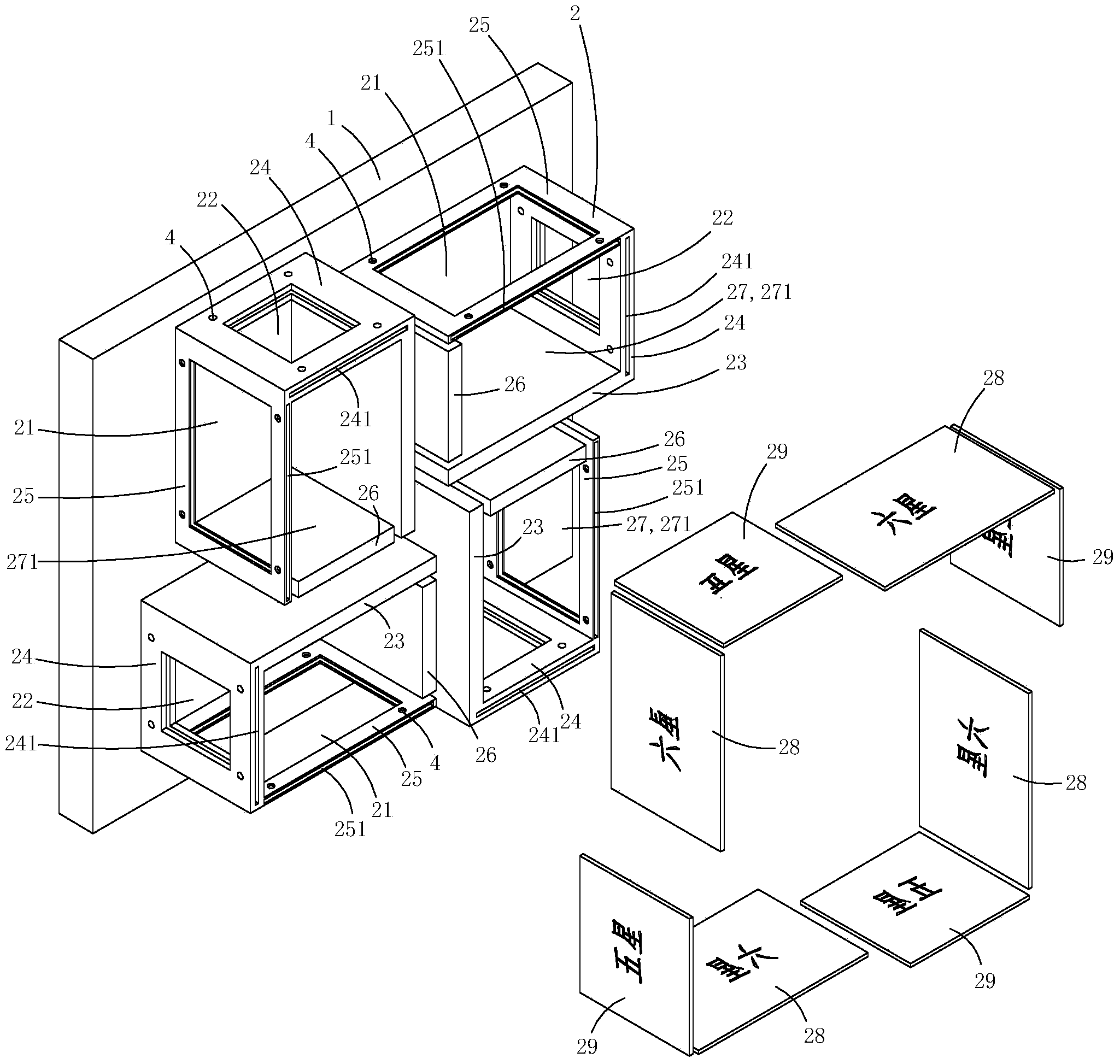
[0014] Figure 1 to Figure 4 A specific embodiment of the invention is shown in which, figure 1 It is a schematic diagram of a three-dimensional structure of the present invention; figure 2 yes figure 1 A schematic diagram of a three-dimensional structure of the laser marking system shown when viewed from another angle; image 3 yes figure 1 An exploded view of the laser marking system shown; Figure 4 yes figure 1 A working schematic diagram of the laser marking system shown.

[0015] This embodiment is an improved laser marking system, see Figure 1 to Figure 3 As shown, it includes a laser head (not shown in the figure) that emits a plane laser, a drive disc 1 that performs circular motion, and four clamps 2 arranged on the drive disc. See image 3 As shown, the plane where the driving disc is located is divided into four stations by dotted lines, along the direction of rotation of the driving disc, there are feeding station 31, first marking station 32, second mar...

Embodiment 2)

[0026] This embodiment is basically the same as Embodiment 1, except that the first baffle or the second baffle is made of light-transmitting materials, such as transparent glass, and the first baffle or the second baffle is pasted with Translucent printing paper with text and patterns to be marked. There are opaque characters and patterns on the light-transmitting printing paper, and the rest is transparent. This structure allows the laser to pass through the transparent part and burn the surface of the workpiece to be marked, while the opaque part of the light-transmitting printing The text and pattern will block the laser from passing through, so as to leave a more distinctive mark to meet the special needs of users.


PUM


Abstract

The invention discloses a novel laser marking system. The system comprises a laser head for transmitting planar laser, a driving disc for doing circling motion and four clamps which are arranged on the driving disc; each clamp comprises a feeding plate, a static clamp plate, a sealing plate and a movable clamp plate, wherein the feeding plates, the static clamp plates, the sealing plates and the movable clamp plates are vertical to the driving discs, the feeding plates are parallel to the sealing plates, the static clamping plates and the movable clamping plates are arranged in parallel, and the static clamp plates are vertical to the sealing plates; a rectangular accommodation cavity is defined by each feeding plate, each static clamp plate, each sealing plate and each movable clamping plate; each sealing plate is provided with a first laser incidence hole, and each static clamp plate is provided with a second laser incidence hole; all sealing plates are provided with first clamp slots, and each static clamp plate is further provided with a second clamp plate; each clamp further comprises a first baffle and a second baffle, wherein each first baffle is used for blocking a first laser incidence hole and is inserted in the corresponding first clamp slot, and each second baffle is inserted into the corresponding second clamp slot and is used for blocking a second laser incidence hole; the first baffles and the second baffles are provided with to-be-marked letters and patterns. According to the novel laser marking system, the manufacturing cost can be effectively reduced.

Description

technical field [0001] The invention belongs to the technical field of laser marking systems. Background technique [0002] Laser marking is to use laser beams to make permanent marks on the surface of various substances. The effect of marking is to expose deep substances through the evaporation of surface substances, or to "engrave" through the chemical and physical changes of surface substances caused by light energy. Traces are produced, or traces are "engraved" by the chemical and physical changes of surface substances caused by light energy, or some substances are burned away by light energy, and the etched patterns and characters are displayed. Laser marking has the advantages of fast marking speed, good continuous working stability, and high positioning accuracy. It is widely used in the marking of graphics and text in various fields such as electronics, hardware, aviation components, auto parts, and metal signs. [0003] Due to the high price of the light control an...

Claims


Application Information

Patent Timeline
Patent Type & Authority Applications(China)
IPC IPC(8): B41J2/435
CPCB23K26/361B23K26/702B23K37/04B41J2/435B41J3/407
Inventor 刘开成
Owner NANTONG MEELAIN ELECTRIC APPLIANCE CO LTD
Learn More