
Dual-output washing machine drum speed reducing clutch and washing machine

The technology of a drum washing machine and a deceleration clutch, which is applied to other washing machines, washing devices, textiles and papermaking, etc., can solve the problems of unsatisfactory washing effect, increased cost and power consumption, and high motor price, so as to improve the washing ratio and save energy. Axial dimension, energy saving effect

Active Publication Date: 2014-09-10
NINGGUO JULONG IND
View PDF6 Cites 18 Cited by
  • Summary
  • Abstract
  • Description
  • Claims
  • Application Information

AI Technical Summary

Problems solved by technology

[0002] There is no deceleration clutch on the existing drum washing machine, the motor drives the inner cylinder to rotate through the deceleration of the pulley, the dehydration speed of the drum washing machine is about 800-1200rpm, and the washing speed is only about 50~60rpm, so a large reduction ratio is required during washing. Usually use a two-speed motor, or rely on a direct drive motor to adjust the speed. Either way will increase the cost and power consumption. Not only the motor is expensive, but also consumes a lot of energy. The washing method is single and the washing effect is not ideal. Looking for a comprehensive washing method The drum clutch and its washing machine are the technical problems we need to solve

Method used


Image

  • Dual-output washing machine drum speed reducing clutch and washing machine
  • Dual-output washing machine drum speed reducing clutch and washing machine
  • Dual-output washing machine drum speed reducing clutch and washing machine

Examples


Embodiment Construction

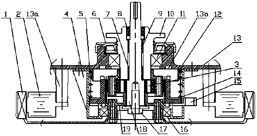
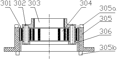
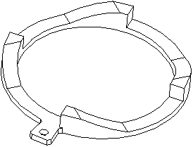
[0026] combine Figure 1-Figure 9 , is a schematic diagram of the principle structure of an embodiment of the deceleration clutch for a double-output drum washing machine of the present invention, which includes an inner cylinder shaft 10, an input shaft 18 placed inside the inner cylinder shaft 10, and an input shaft 18 placed between the inner cylinder shaft 10 and the input shaft 18. Between the wheel train assembly 3, the input shaft 18 is concentrically installed in the inner cylinder shaft 10 through the lower bush 7 and the upper bush 9, the input shaft 18 is the first output, and is connected with the rotor 1 through the rotor mounting plate 19, The inner cylinder shaft 10 is the second output, connected to the input shaft 18 through the gear train assembly 3; the gear train assembly includes planetary gear 301, planetary shaft 302, planetary carrier 303, sun gear 304, internal gear 305 and planetary carrier Cover 306, the planetary gear 301 is installed on the planeta...


PUM


Abstract

The invention discloses a dual-output washing machine drum speed reducing clutch and a washing machine, relates to the technical field of washing machines and overcomes the defect of unexpected washing effect of an existing washing machine. The dual-output washing machine drum speed reducing clutch comprises an internal drum shaft and is characterized by further comprising an input shaft arranged in the internal drum shaft and a gear set component arranged between the internal drum shaft and the input shaft; the input shaft is concentrically mounted in the internal drum shaft through a lower lining sleeve and an upper lining sleeve; the input shaft is of a first output and is connected to a rotor through a rotor mounting plate; the internal drum shaft is of a second output and is connected to the input shaft through the gear set component; a stirrer of the washing machine is mounted in an internal drum and is connected to the input shaft. Thus, washing efficiency is improved, the axial size is saved, the stirrer and the internal drum are the same in rotating direction and are different in rotating speed, dual-power washing is implemented, stirring and rolling actions is added when clothing is tossed, beat, and tossed again, cleaning ratio is increased, heating is omitted, and power is saved.

Description

technical field [0001] The invention relates to the technical field of drum washing machines, in particular to a deceleration clutch for double-output drum washing machines. Background technique [0002] There is no deceleration clutch on the existing drum washing machine, the motor drives the inner cylinder to rotate through the deceleration of the pulley, the dehydration speed of the drum washing machine is about 800-1200rpm, and the washing speed is only about 50~60rpm, so a large reduction ratio is required during washing. Usually a two-speed motor is used, or a direct drive motor is used to adjust the speed. Either way will increase the cost and power consumption. Not only the motor is expensive, but also consumes a lot of energy. The washing method is single and the washing effect is not ideal. Looking for a comprehensive washing method The drum clutch and its washing machine are technical problems that we need to solve. Contents of the invention [0003] The first ...

Claims


Application Information

Patent Timeline
IPC IPC(8): D06F37/30D06F37/40
CPCD06F37/30D06F37/40
Inventor 刘军
Owner NINGGUO JULONG IND
Learn More