Bearing chamber oil and gas two-phase flow and heat exchange testing device

A technology of bearing cavity and heat test, which is applied in the direction of aerodynamic test, fluid dynamic test, measuring device, etc., can solve the problems of reducing the convenience of replacement, inability to connect and disconnect, large deformation of the right cover plate, etc., to achieve Effects of reducing current signal interference, quick installation and disassembly, and simplified lubrication structure

Inactive Publication Date: 2014-09-10
NORTHWESTERN POLYTECHNICAL UNIV
View PDF6 Cites 23 Cited by
  • Summary
  • Abstract
  • Description
  • Claims
  • Application Information

AI Technical Summary

Problems solved by technology

The two exhaust ports of the bearing cavity tester are designed to be open, and the oil mist flowing out of the exhaust port of the bearing cavity is discharged to the atmosphere, resulting in wasting lubricating oil and polluting the environment
Multiple sets of pressure sensors and thermal resistors in the data acquisition subsystem are directly connected to the data collector, resulting in confusion in the connection of the wires. The electrical signals in the wires interfere with each other, reducing the quality of the measurement signal. The pressure sensors, thermal resistors and data collectors are not independent. The connector plug, so it cannot be connected and disconnected flexibly
The high-speed motor in its power subsystem is connected to the rotating shaft through a pin coupling. The pin coupling easily transmits the vibration of the motor to the rotating shaft in the bearing cavity, causing the vibration of the bearing cavity tester to affect the flow state of the oil-gas medium and the pressure and temperature signals. stable measurement
[0005] In the above two documents, when the width and height of the chamber of the test device are changed, it is necessary to replace the whole set of parts such as the chamber and the end cover. On the one hand, the convenience of replacement is reduced; The cost of components is high; in addition, the lubricating oil in the test device is contained in an oil tank, which makes it difficult to control the temperature of the lubricating oil in the oil tank, and the mixing of return oil and oil supply in the oil tank is not conducive to the precipitation of air in the lubricating oil
The right end cover of the two test devices is a whole piece of plexiglass, and the strength of the right cover plate is insufficient. When the cavity vibrates, the right cover plate deforms greatly, resulting in uneven sealing gaps when the test system is working, which affects the stability of the air flow into the bearing cavity.
The other two test devices cannot obtain the image information of the oil-gas two-phase flow state in the bearing cavity corresponding to the collected pressure and temperature, which cannot meet the needs of a comprehensive understanding of the state of the oil-gas medium in engineering design and theoretical analysis.

Method used


Image

  • Bearing chamber oil and gas two-phase flow and heat exchange testing device
  • Bearing chamber oil and gas two-phase flow and heat exchange testing device
  • Bearing chamber oil and gas two-phase flow and heat exchange testing device

Examples


Embodiment Construction

[0066] Describe the present invention below in conjunction with embodiment:

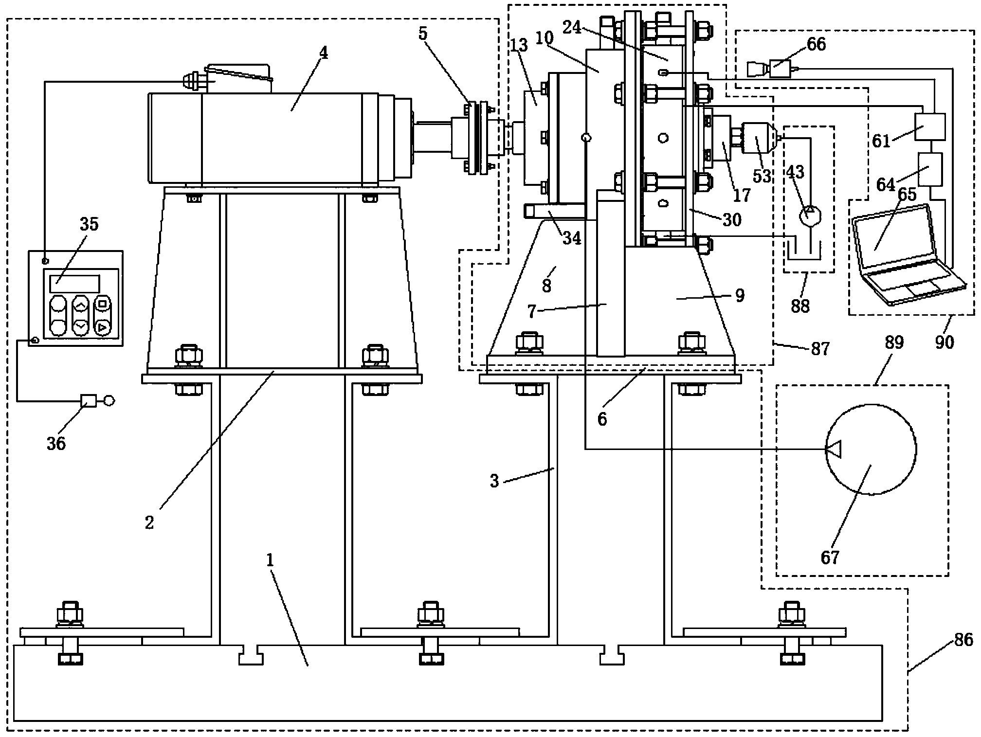
[0067] Refer to attached figure 1 , The bearing chamber oil-gas two-phase flow and heat transfer test device described in this embodiment includes a power and support system 86 , a bearing chamber mechanical body 87 , a lubricating oil circulation system 88 , an air supply system 89 and a measurement camera system 90 .

[0068] Refer to attached figure 1 On the one hand, the power and support system 86 is used to support the high-speed variable-frequency motor 4 and the mechanical body 87 of the bearing cavity, and on the other hand, it is used to adjust the speed of the high-speed variable-frequency motor 4, that is, to adjust the speed of the test bearing 18. In this embodiment, the power components include a high-speed variable frequency motor, a diaphragm coupling, a frequency converter and an air switch. The downstream of the frequency converter 35 is connected to the high-speed variable-frequ...


PUM


Abstract

The invention provides a bearing chamber oil and gas two-phase flow and heat exchange testing device. The structure that a testing bearing and a shaft are directly arranged in a sleeved mode is designed. An oil transportation hole or groove is designed in the inner ring of the testing beaming or the inner ring of the shaft. A testing beaming lubricating structure is simplified under the circumstance that under-ring lubrication of the testing beaming is guaranteed. An electric heating type chamber body heating structure is designed, and the structure of the electric heating type chamber body heating structure is simplified compared with a tap water heating and cooling method, so that cost is reduced. Bearing chamber geometric structures of different sizes can be realized through replacement of axial distance rings of different sizes and radial distance rings of different sizes, and the cost of manufacturing a chamber body is reduced. An oil scavenger pump is additionally arranged so that oil can return smoothly, and the lubricating oil does not accumulate in a chamber. An exhaust vent is connected with an oil return tank through an oil way, so that the situation that oil mist is exhausted from an exhaust pipe and pollutes the environment is avoided, and waste of the lubricating oil is avoided. A high-speed camera is arranged to shoot oil and gas conditions inside the bearing chamber, so that oil and gas condition images and pressure and temperature signals are recorded on a computer synchronously.

Description

technical field [0001] The invention relates to a test device, in particular to a test device for oil-gas two-phase flow and heat exchange in a bearing cavity. Background technique [0002] The bearing cavity is one of the components of the lubrication system of the aero-engine. The lubricating oil used to lubricate and cool the rolling bearings and the sealing air to prevent the leakage of the lubricating oil form a lubrication condition of two-phase flow of oil and gas in the bearing cavity. The design of the engine lubrication system and the secondary air system depends on the correct understanding and accurate calculation of the oil-gas two-phase flow and heat transfer in the bearing cavity. Carrying out the oil-gas two-phase flow and heat transfer test in the bearing cavity is an important part of the engineering design and theoretical analysis of the bearing cavity. Therefore, it is necessary to design a corresponding test device. [0003] The document "Influence of h...

Claims


Application Information

Patent Timeline
Patent Type & Authority Applications(China)
IPC IPC(8): G01M9/00G01M10/00G01M13/00G01N25/20
Inventor 陈国定孙恒超陈薄王涛王菲
Owner NORTHWESTERN POLYTECHNICAL UNIV
Why Eureka
Try Eureka