Motor control device

A technology of motor control and current vector, applied in the direction of motor generator control, AC motor control, control of electromechanical transmission devices, etc., can solve the problems of no reflection, reduction of pulsating torque suppression effect, etc., and achieve the effect of suppressing pulsating torque

Active Publication Date: 2014-09-10
HITACHI JOHNSON CONTROLS AIR CONDITIONING INC
View PDF5 Cites 149 Cited by
  • Summary
  • Abstract
  • Description
  • Claims
  • Application Information

AI Technical Summary

Problems solved by technology

However, since the phase of the pulsating component of the shaft error is not reflected when the uppe

Method used


Image

  • Motor control device
  • Motor control device
  • Motor control device

Examples


no. 1 Embodiment approach 》

[0029]

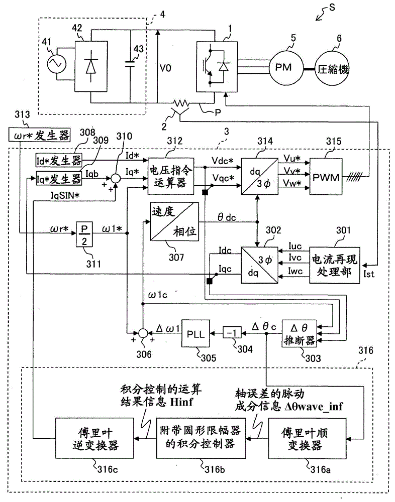
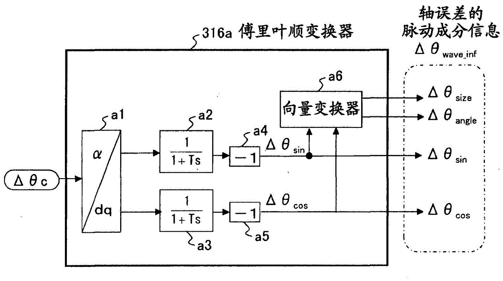
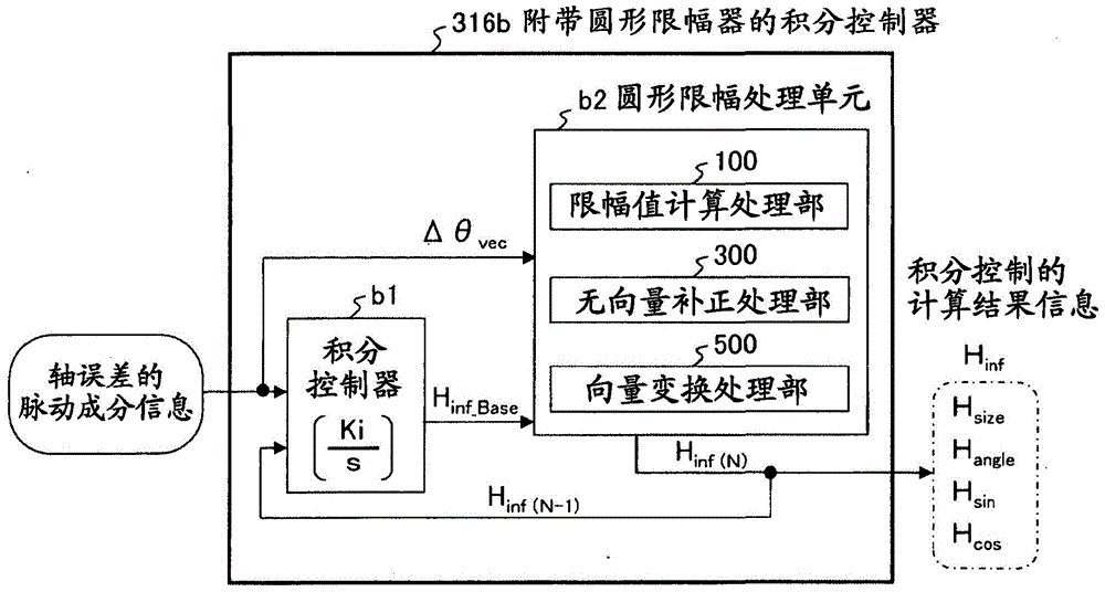
[0030] figure 1 It is a configuration diagram of the motor control device according to the present embodiment. figure 1 The illustrated motor control system S is a system that drives a compressor 6 (for example, a rotary compressor) by controlling the output voltage of the inverter 1 to rotate a rotor (not shown) of an AC motor 5 . The motor control system S includes an inverter 1 , a current sensor 2 , and a motor control device 3 .

[0031] The inverter 1 is a power converter that converts the DC voltage V0 input from the DC power supply 4 into a three-phase AC voltage, and outputs it to the AC motor 5 . Here, the DC power supply 4 is a device that converts AC power input from the AC power supply 41 into DC power using a rectifier circuit 42 and a smoothing capacitor 43 .

[0032] The inverter 1 has a plurality of switching elements (not shown), and converts the DC voltage V0 into a three-phase AC voltage by switching ON / OFF of the switching elements according t...

no. 2 Embodiment approach

[0112] The circular clipping processing unit b2 of the motor control device 3 of the second embodiment (refer to image 3 ) equipped with no vector value correction processing unit 300A (refer to image 3 ) is different from that of the first embodiment, and the others are the same as those of the first embodiment. Therefore, the different parts will be described, and the description of the parts overlapping with the first embodiment will be omitted.

[0113] (Without vector value correction processing unit)

[0114] Figure 10It is a configuration diagram of a non-vector correction processing unit included in the circular clipping processing unit of the motor control device according to the present embodiment.

[0115] In this embodiment, the circular clipping processing unit b2 is characterized in that no variation tolerance range (equivalent to the rectangular range A described in the first embodiment: refer to Figure 9 ) to perform circular clipping processing.

[01...


PUM


Abstract

A motor control device capable of suitably inhibiting the pulsating torque of an alternating-current motor is provided. The motor control device comprises an axis error inference machine (30) which infers an axis error based on a current value of an inverter, detected by a current sensor (2); a Fourier rectification machine (316a) which extracts an axis error vector from the time-base changes of the axis error; an integral control machine (316b) additionally provided with a circular amplitude limiter, which is used to calculate a correction current vector for offsetting the pulsating torque, wherein a circle with a set amplitude limiting value serving as the radius is used as the base for limiting the movement of the correction current vector, and the integral control machine (316b) additionally provided with the circular amplitude limiter performs the circular amplitude limiting for limiting the movement of the correction current vector so as to enable the deflection angle of the correction current vector to be close to the deflection angle of the axis error vector.

Description

technical field [0001] The present invention relates to a motor control device for controlling the drive of an AC motor using a position sensorless device. Background technique [0002] There is known a position sensorless control in which the position of the rotor of the AC motor is estimated from the current detection value of the inverter, and the drive of the AC motor is controlled based on the estimated position. The AC motor driven by position sensorless control has excellent environmental resistance and is especially useful when driving a compressor. [0003] However, when the AC motor is controlled to drive the compressor, the load torque of the AC motor pulsates in synchronization with the compression stroke. Particularly in the case of rotary compressors and reciprocating compressors, pulsation of load torque synchronous with the compression operation remarkably occurs. Therefore, when these compressors are driven, it is required to appropriately perform ripple t...

Claims


Application Information

Patent Timeline
IPC IPC(8): H02P21/05H02P27/08H02P21/00H02P21/18H02P21/24H02P23/04H02P25/022H02P25/026H02P27/04
CPCH02P6/18H02P21/0003H02P21/20H02P25/089H02P27/04
Inventor 樋爪达也小仓洋寿B·斯瓦潘铃木尚礼
Owner HITACHI JOHNSON CONTROLS AIR CONDITIONING INC
Why Eureka
Try Eureka