Light source equipment used for treating vagina inflammatory diseases of gynecology

A light source and vaginal technology, applied in the field of medical and health care equipment, can solve the problems of inconvenience for patients to go out, large volume, unfavorable health care and prevention, etc.

Active Publication Date: 2014-09-17
王翔宇
View PDF10 Cites 11 Cited by
  • Summary
  • Abstract
  • Description
  • Claims
  • Application Information

AI Technical Summary

Problems solved by technology

However, because such diseases belong to the privacy of patients, and the time and environment of hospital visits often cause inconvenience to patients, it is difficult for them to obtain sufficient therapeutic effects.
Moreover, the current physiotherapy equipment has a large

Method used


Image

  • Light source equipment used for treating vagina inflammatory diseases of gynecology
  • Light source equipment used for treating vagina inflammatory diseases of gynecology
  • Light source equipment used for treating vagina inflammatory diseases of gynecology

Examples


Embodiment 1

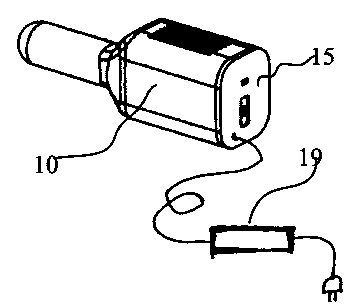
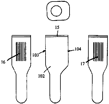
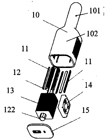
[0025] figure 1 It is a schematic diagram of the overall appearance of the light source device used in the treatment of gynecological vaginal inflammation provided in this embodiment, figure 2 It is a schematic diagram of its structural decomposition. Such as figure 1 with figure 2 As shown, the light source device includes: a housing 10 with a front end 101 and a rear end 102, wherein the front end 101 is cylindrical and the rear end 102 is prism-shaped, and the inner diameter of the front end 101 is smaller than the size between the two opposite side walls of the rear end 102 The multi-point strip light source 11 is formed by installing a plurality of LED light sources on the strip-shaped metal-based printed circuit board 18, and is placed in the front end 101 of the above-mentioned housing; The front end 101 extends to the rear end 102 of the casing, which is used to take away the heat generated when the above-mentioned strip light source 11 works; Quickly dissipate; ...

Embodiment 2

[0033] The difference between this embodiment and the second embodiment is that, in this embodiment, the positions of the air inlet 26 and the air outlet 27 are changed. Figures 5a-5b are schematic diagrams of the appearance of the light source device provided in this embodiment at different angles, Image 6 It is a schematic diagram of the structural decomposition of the light source device, Figures 7a-7c They are the front view, A-A sectional view and B-B sectional view of the light source device respectively.

[0034] Such as Figure 5b with Figure 7b As shown, in this embodiment, the air inlet 26 is disposed on the side wall of the housing 20 , to be precise, it is disposed on the side wall of the housing 20 near the intersection of the front end 201 and the rear end 202 . Moreover, in order to accelerate the effect of air intake, preferably, air intake openings can be provided at corresponding positions of the plurality of side walls of the casing 20 . In contrast,...


PUM

PropertyMeasurementUnit
Wavelengthaaaaaaaaaa

Abstract

The invention mainly provides light source equipment used for treating vagina inflammatory diseases of the gynecology. The light source equipment comprises a shell, a multi-point band-shaped light source, a heat conduction pipe, an air inlet, an air outlet, a cooling device and a rear cover matched with the shell, wherein the multi-point band-shaped light source and the cooling device are arranged at the two ends of the heat conduction pipe, the multi-point band-shaped light source is located in the front transparent end of the shell, and the front transparent end is made to be in an intervention type and can be inserted into the vagina. The light source equipment is convenient for a patient to use, small in overall size and convenient to carry by the patient. In consideration of the right of privacy, the patient can conveniently perform treatment by himself at appropriate time and does not need to be limited by the treatment condition of a hospital, and the light source equipment is small in size and convenient to carry and can fully guarantee the treatment or health care effect of the patient and protect the right of privacy of the patient. In addition, the light source equipment has an obvious effect on microcirculation of the whole pelvic cavity and general care and can effectively reduce the attack rate of the vagina inflammatory diseases.

Description

technical field [0001] The invention mainly relates to the field of medical and health care instruments, in particular to instruments for the treatment or health care of various gynecological vaginitis and the like. Background technique [0002] Gynecological vaginitis, cervicitis, adnexitis, cervical erosion and vaginal ulcers are common and frequently-occurring diseases. In addition to drug treatment, the current practice also includes treatment of physical factors such as phototherapy in the physiotherapy department of the hospital. However, because such diseases belong to the privacy of patients, and the time and environment of hospital visits often cause inconvenience to patients, it is difficult to make them obtain sufficient therapeutic effects. Moreover, the current physiotherapy equipment has a large volume and is inconvenient for patients to go out and carry, which causes many patients to be unwilling to treat, or cannot guarantee the treatment time and frequency,...

Claims


Application Information

Patent Timeline
IPC IPC(8): A61N5/06
Inventor 王翔宇
Owner 王翔宇
Why Eureka
Try Eureka