Method for trimming resin base circle arc diamond grinding wheel by adopting rotary green silicon carbide grinding bar

A diamond grinding wheel and green silicon carbide technology, which is applied to the parts of grinding machine tools, metal processing equipment, grinding/polishing equipment, etc., can solve the problems of low machining accuracy, deviation of the grinding wheel installation position, workpiece shape accuracy, etc., and achieve processing efficiency High, high trimming accuracy, the effect of improving shape accuracy

Active Publication Date: 2014-09-17
HARBIN INST OF TECH
View PDF8 Cites 15 Cited by
  • Summary
  • Abstract
  • Description
  • Claims
  • Application Information

AI Technical Summary

Problems solved by technology

[0005] The purpose of the present invention is to solve the problem that the deviation of the installation position of the grinding wheel in the vertical direction affects the shape accuracy of the processed workpiece and the processing accuracy is low. It provides a resin-based arc-shaped diamond grinding wheel that uses a rotating green silicon carbide grinding rod. Methods

Method used


Image

  • Method for trimming resin base circle arc diamond grinding wheel by adopting rotary green silicon carbide grinding bar
  • Method for trimming resin base circle arc diamond grinding wheel by adopting rotary green silicon carbide grinding bar

Examples


specific Embodiment approach 1

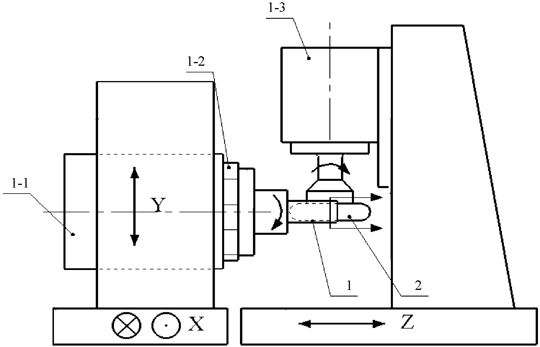
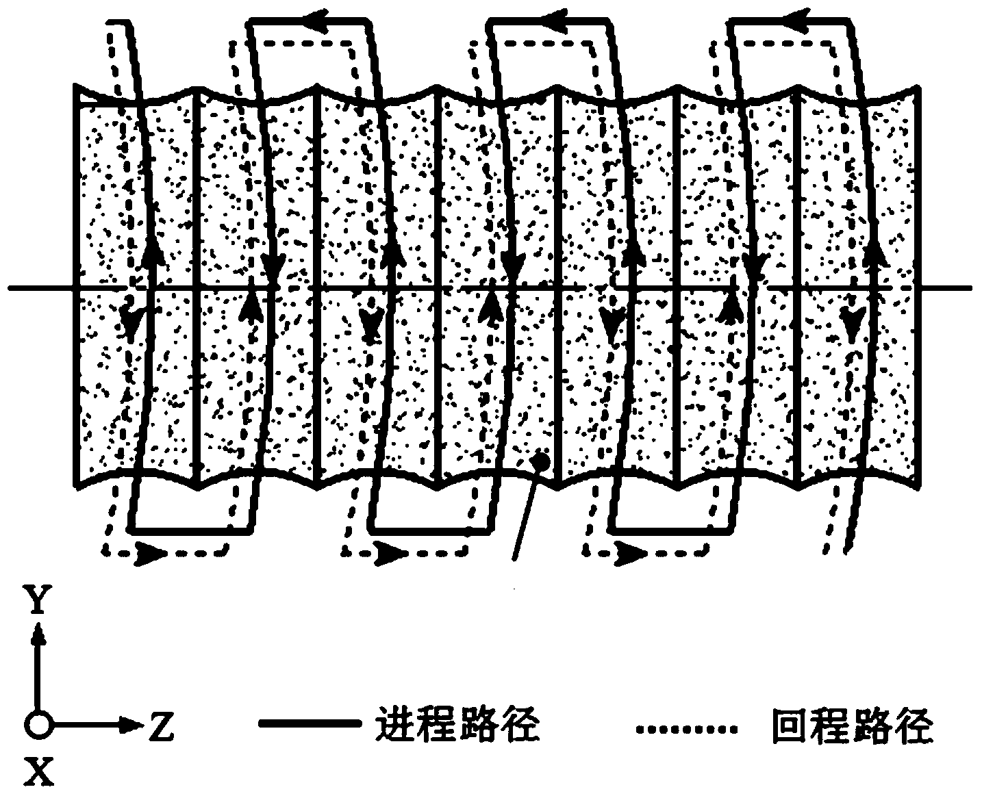
[0023] Specific implementation mode one: the following combination figure 1 and figure 2 Illustrate the present embodiment, the method for using the rotating green silicon carbide grinding rod to dress the resin-based arc-shaped diamond grinding wheel described in the present embodiment is characterized in that it comprises the following steps:

[0024] Step 1: Install the green silicon carbide grinding rod 1 on the vacuum chuck 1-2 of the workpiece spindle 1-1 of the three-linear axis linkage machine tool, and install the grinding wheel 2 on the lower end of the grinding spindle 1-3 of the three-linear axis linkage machine tool Department, adjust the initial positional relationship between the green silicon carbide grinding rod 1 and the grinding wheel 2 through the vertical Y spindle, horizontal X spindle and horizontal Z spindle of the three-linear axis linkage machine tool; The position in the XY plane is controlled by the Y spindle in the vertical direction and the X sp...

specific Embodiment approach 2

[0028] Specific implementation mode two: the following combination figure 1 This embodiment will be described. This embodiment will further explain the first embodiment. The vertical Y spindle, the horizontal X spindle and the horizontal Z spindle of the three-linear axis linkage machine tool are used to adjust the green silicon carbide grinding rod 1 and the grinding wheel 2. The specific method of the initial position relationship is:

[0029] First, determine the Y-direction position of the center plane of the grinding wheel 2 and the green silicon carbide grinding rod 1:

[0030] Move the Y spindle in the vertical direction so that the green silicon carbide grinding rod 1 is in contact with the upper surface of the abrasive layer of the grinding wheel 2, and record the Y-direction position coordinate Y of the workpiece spindle 1-1 axis at this time 1 , move the Y spindle in the vertical direction to make the green silicon carbide grinding rod 1 contact the lower surface o...

specific Embodiment approach 3

[0037] Embodiment 3: This embodiment further describes Embodiment 1 or 2, and the value of B ranges from 3 to 5 mm.


PUM


Abstract

The invention provides a method for trimming a resin base circle arc diamond grinding wheel by adopting a rotary green silicon carbide grinding bar, and belongs to the technical field of machining of the resin base circle arc grinding wheel. The method aims to solve the problems that the installation position deviation, in the vertical direction, of the grinding wheel in a grinding process affects the shape accuracy of a machined workpiece, and machining accuracy is low. The method comprises the steps that firstly, the green silicon carbide grinding bar is arranged on a vacuum chuck of a workpiece main shaft of a three-linear-axis linkage machine tool, and the grinding wheel is arranged at the lower end of a grinding main shaft of the three-linear-axis linkage machine tool; then, a trimming path of the grinding wheel is planned, and the grinding wheel starts to be trimmed; every time the next adjacent interpolation period T starts, the radius R of the current green silicon carbide grinding bar is collected, the trimming path is corrected, and the grinding wheel continues to be trimmed by adopting the corrected trimming path until trimming is completed. The method is used for trimming the resin base circle arc diamond grinding wheel.

Description

technical field [0001] The invention relates to a method for dressing a resin-based arc-shaped diamond grinding wheel by using a rotating green silicon carbide grinding rod, and belongs to the processing technical field of the resin-based arc-shaped grinding wheel. Background technique [0002] In recent years, spherical, aspherical and free-form optical parts have been more and more widely used in military and civilian products. For these optical parts, which are mostly made of hard and brittle materials such as ceramics, optical glass, and hard alloys, super Precision grinding technology is an effective solution for its preparation. Commonly used forming grinding methods for optical parts mainly include vertical grinding and parallel grinding. The vertical grinding method uses the top of the V-shaped grinding wheel or the abrasive grain layer in the center of the arc-shaped grinding wheel to grind the workpiece according to the formed numerical control trajectory. This pr...

Claims


Application Information

Patent Timeline
Patent Type & Authority Applications(China)
IPC IPC(8): B24B53/06B24B53/12
CPCB24B53/062B24B53/065B24B53/12
Inventor 陈冰赵清亮郭兵饶志敏葛成
Owner HARBIN INST OF TECH
Why Eureka
Try Eureka