Pavement repairing method capable of resolving settlement velocity difference between hard soil and soft soil

A technology for road surface repair and hard soil layer, applied in the direction of road, road, bridge maintenance, etc., can solve problems such as the difference in settlement velocity between hard soil layer and soft soil layer, achieve short curing time, reduce construction time, and avoid bridgehead jumping. Effect

Active Publication Date: 2014-09-17
JIANGSU DINGTAI ENG MATERIAL
7 Cites 0 Cited by

AI-Extracted Technical Summary

Problems solved by technology

[0005] The technical problem to be solved by the present invention is to provide a pavement repair method t...

Method used

Slurry described in the present invention adopts a kind of high-strength foaming type resin, and its model is SZ3, and this resin is added in above-mentioned grouting equipment during grouting, the resin viscosity that flows out from this grouting equipment ( Exit viscosity) is 100±45mPa·s. The volume of the resin slurry increases continuously during the flow, and its penetrat...

Abstract

The invention relates to a pavement repairing method. The method comprises the following steps: using radar detection to detect the void position in the slab of s damaged bridge, marking the position of grouting holes 1 on the slab surface of locating and drilling, wherein the grouting holes reach the hard soil and are arranged in array, center distance of adjacent grouting holes is 10-20 cm and the void falls into the array range; penetrating the grouting holes 2 through the soft soil and intersecting with grouting holes 1, and arranging exhaust one-way valves at two ends of each grouting hole 2; grouting into the grouting holes 1 and using three-dimensional radar to detect the slurry grouting condition in the void, grouting holes 1 and grouting holes 2 on a real-time basis, and filling the void, the grouting holes 1 and grouting holes 2 with slurry, and stopping grouting; and after grouting, using detection radar to detect and review the filling portions, and re-drilling and grouting the position without slurry filling. The method solves the problem of settlement velocity difference between hard soil and soft soil.

Application Domain

Paving detailsBridge strengthening +1

Technology Topic

Soil horizonSoil science +3

Image

  • Pavement repairing method capable of resolving settlement velocity difference between hard soil and soft soil
  • Pavement repairing method capable of resolving settlement velocity difference between hard soil and soft soil
  • Pavement repairing method capable of resolving settlement velocity difference between hard soil and soft soil

Examples

  • Experimental program(2)

Example Embodiment

[0033] Example 1
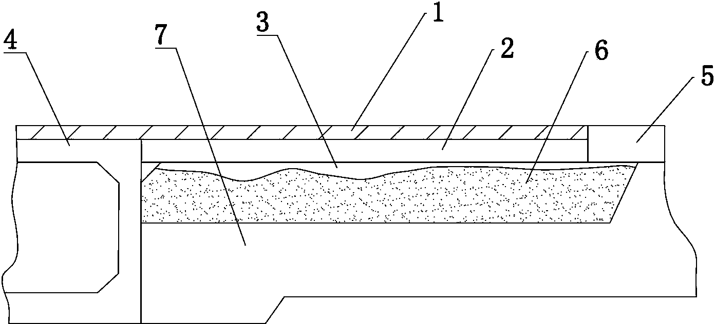
[0034] Such as figure 1 As shown, the damaged bridge generally includes: pavement surface 1, slab 2, void 3, bridge surface 4, road surface 5, soft soil layer 6, and hard soil layer 7.
[0035] Void generally occurs between the slab 2 and the soft soil layer 6. The void volume will gradually increase with the settlement of the soft soil layer. Since the soft soil layer 6 is higher than the roadbed, it is convenient to drill the soft soil layer 6 from the side. hole.
[0036] Such as figure 1 -As shown in 3, a road repair method of the present invention includes the following steps:
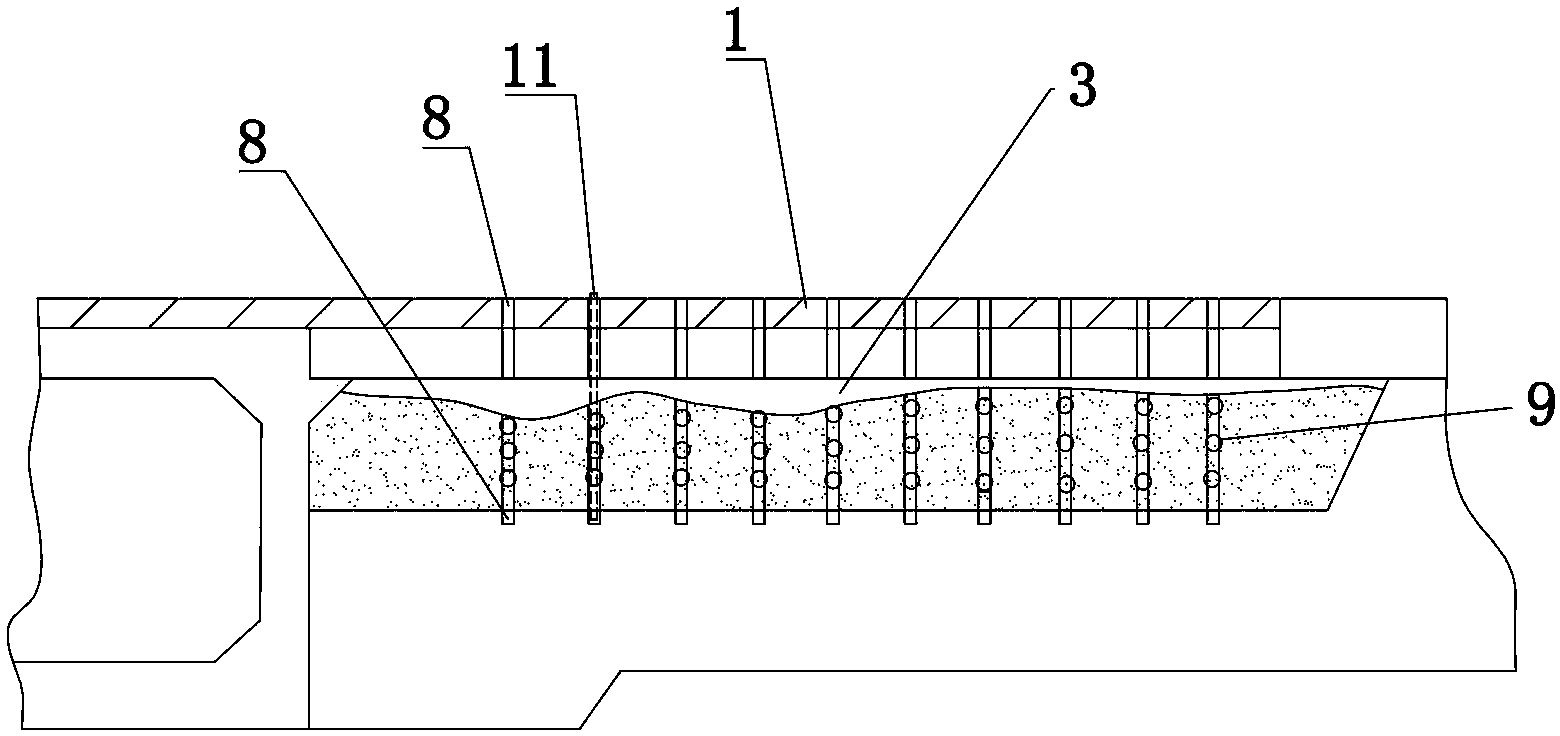
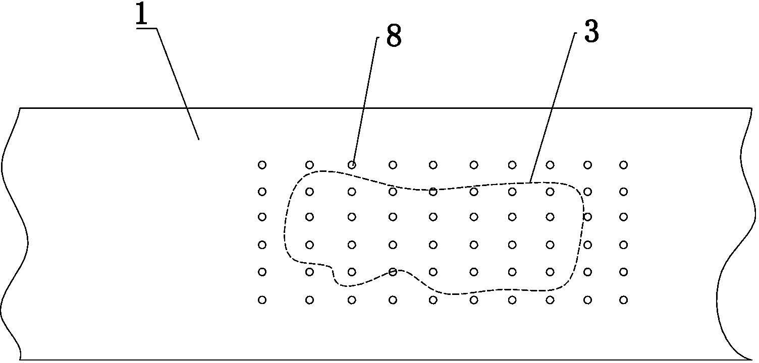
[0037] (1) Use a three-dimensional detection radar or ultrasonic detection device to detect the void 3 position in the slab of the damaged bridge, mark the void 3 position on the surface of the slab 2, and measure the void 3 and the hard soil layer 7 depth;
[0038] (2) Mark the position of each grouting hole 8 on the surface of the slab 2 above the void 3 and drill holes. The diameter of the grouting hole 8 is 5-10cm and the depth reaches the hard soil layer 7. All grouting holes One 8 is arranged in a square array, the center spacing of adjacent grouting holes 8 is 10-20 cm, and the above-mentioned marked void 3 falls within the array range of the grouting holes 8;
[0039] (3) Mark the positions of grouting holes 9 on the side of the soft soil layer 6 and drill holes. Each grouting hole 9 horizontally penetrates the soft soil layer and intersects with a grouting hole 8. 8 Intersect with three grouting holes 9 located below the void 3, each grouting hole 9 is perpendicular to the center line of the slab and has a diameter of 5-10cm;
[0040] (4) Install the grouting pipe 11 at the position of each grouting hole 8 and extend the grouting pipe 11 to the bottom of the grouting hole 8, install grouting joints on each grouting pipe 11, debug the grouting equipment and Connect with the grouting joint, check the grouting material and add it to the grouting equipment. At both ends of each grouting hole 9 there is a one-way valve that can only discharge air;
[0041] (5) Perform grouting on the grouting hole 8 and use the three-dimensional detection radar to detect the void 3 and the filling of the slurry inside each grouting hole 8 and grouting hole 2 9. When the slurry is full of the void 3 And each grouting hole 8 and grouting hole 2 will stop grouting at 9;
[0042] (6) After the grouting is stopped, use the detection radar to detect the void 3 and each grouting hole 8 and grouting hole 2 9 whether there are any parts that are not filled with slurry, and re-drill the positions where the above conditions exist , Grouting;
[0043] (7) After waiting for 10 minutes, the filled slurry solidifies and reaches the final strength, remove the one-way valve and seal each grouting hole 8 and grouting hole 2.
[0044] The cured slurry forms as Figure 4 The slurry body 10 shown includes multiple rows of a network structure composed of a plurality of vertical slurry pillars 101, horizontal slurry beams 103, and a slurry layer 102 filled with voids 3. The slurry body 10 is The board 2, the soft soil layer 6 and the hard soil layer 7 are fixedly connected.

Example Embodiment

[0045] Example 2
[0046] The slurry described in the present invention adopts a high-strength foaming resin whose model is SZ3. The resin is added to the above-mentioned grouting equipment during grouting, and the viscosity of the resin flowing out of the grouting equipment (out-machine viscosity) ) Is 100±45mPa·s. The volume of the resin slurry increases continuously in flow, and its permeability is strong. It is suitable for quickly reaching the void or entering the gap. It is suitable for squeezing out water under pressure. The slurry can be filled and emptied after 3 minutes of injection, and its final strength will be reached after 10 minutes of injection, with its compressive strength ≥20MPa and bending strength ≥15MPa.
[0047] The slurry has the following characteristics:
[0048] (1) The slurry does not contain water, does not produce dry shrinkage, and can be densely filled and void; the slurry is flexible and elastic after curing, and it is not easy to crack. At the same time, the resin material has good impermeability and can prevent Rainwater penetrates into the soft soil layer and has a good sealing effect on cracks and joints;
[0049] (2) After the slurry is solidified, it will form a foamed solid with a density of 20% of the cement slurry, which will not cause a large load on the structure;
[0050] (3) The free expansion ratio of the slurry can reach 20:1, which can quickly fill the void, and further compact the surrounding soil layer during the expansion process;
[0051] (4) The cured slurry has strong stability, is not easy to be aging and deformed, and its durability can reach a hundred years;
[0052] (5) After the slurry is solidified, the chemical components will not be dissolved or decomposed in the rainwater and lost, and there is no pollution to the environment;
[0053] (6) The slab structure repaired by the slurry does not require regular maintenance and maintenance in the later period, which reduces the maintenance cost.

PUM

PropertyMeasurementUnit
Diameter3.0 ~ 15.0cm
Compressive strength>= 20.0mPa
Bending strength>= 15.0mPa

Description & Claims & Application Information

We can also present the details of the Description, Claims and Application information to help users get a comprehensive understanding of the technical details of the patent, such as background art, summary of invention, brief description of drawings, description of embodiments, and other original content. On the other hand, users can also determine the specific scope of protection of the technology through the list of claims; as well as understand the changes in the life cycle of the technology with the presentation of the patent timeline. Login to view more.

Similar technology patents

Fine dried noodle drying method

InactiveCN104026179ANot easy to crackImprove the quality of dried noodles
Owner:BEIDAHUANG FENGYUAN GRP +1

Separating-connecting type safety anti-theft lock

ActiveCN107806286Anot easy to crackImprove anti-theft security performance
Owner:上海英特罗机械电气制造股份有限公司

Aluminum air conditioner foil with breathability and preparation method thereof

ActiveCN105459499Anot easy to crackHigh flanging height
Owner:苏州福羊自控科技有限公司

Composite nano-propylene pigment and preparation method thereof

InactiveCN109135463Anot easy to cracknot easy to mold
Owner:苏州德加画材科技有限公司

Classification and recommendation of technical efficacy words

  • not easy to crack

Flexible tile adhesive

InactiveCN105645860AStrong bonding abilitynot easy to crack
Owner:SHUN TAN SHANGHAI NEW MATERIALS CO LTD

Sealing coating composition of kiln

InactiveCN101613208Anot easy to crackprevent air leakage
Owner:王宏伟
Why Eureka
Try Eureka