Hydraulic power pack structure of hydraulic press of jack

A technology of hydraulic pump station and press, applied in the field of press machinery, can solve the problems of difficult processing, complex valve body oil circuit structure, etc., and achieve the effect of simple structure and convenient processing

Active Publication Date: 2014-09-17
CHANGSHU TONGRUN AUTO REPAIRING EQUIP
View PDF16 Cites 2 Cited by
  • Summary
  • Abstract
  • Description
  • Claims
  • Application Information

AI Technical Summary

Problems solved by technology

However, this patent application scheme has the disadvantage that the oil circuit structure of the valve body is complex and the processing is difficult.

Method used


Image

  • Hydraulic power pack structure of hydraulic press of jack
  • Hydraulic power pack structure of hydraulic press of jack
  • Hydraulic power pack structure of hydraulic press of jack

Examples


Embodiment 1

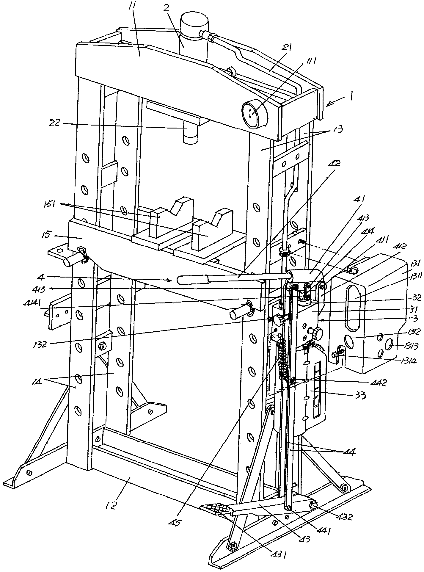
[0023] See figure 1 ,Should figure 1 A frame 1 is provided, which is composed of an upper beam 11, a lower beam 12, a first longitudinal arm 13, a second longitudinal arm 14 and a workpiece rack 15, and the upper and lower beams 11, 12 correspond to each other up and down, The upper end of the first longitudinal arm 13 is fixedly connected with the right end of the upper beam 11, and the lower end of the first longitudinal arm 13 is fixedly connected with the right end of the lower beam 12, and the upper end of the second longitudinal arm 14 is fixedly connected with the left end of the upper beam 11, and The lower end of the second longitudinal arm 14 is fixedly connected to the left end of the lower crossbeam 12, so that the frame 1 is formed by the upper and lower crossbeams 11, 12 and the first and second longitudinal arms 13, 14 parallel to each other longitudinally to form a structure similar to Chinese characters. The "mouth"-shaped structure, the workpiece frame 15 is...

Embodiment 2

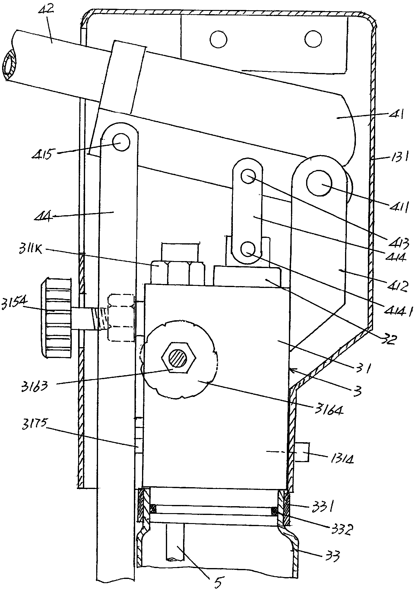
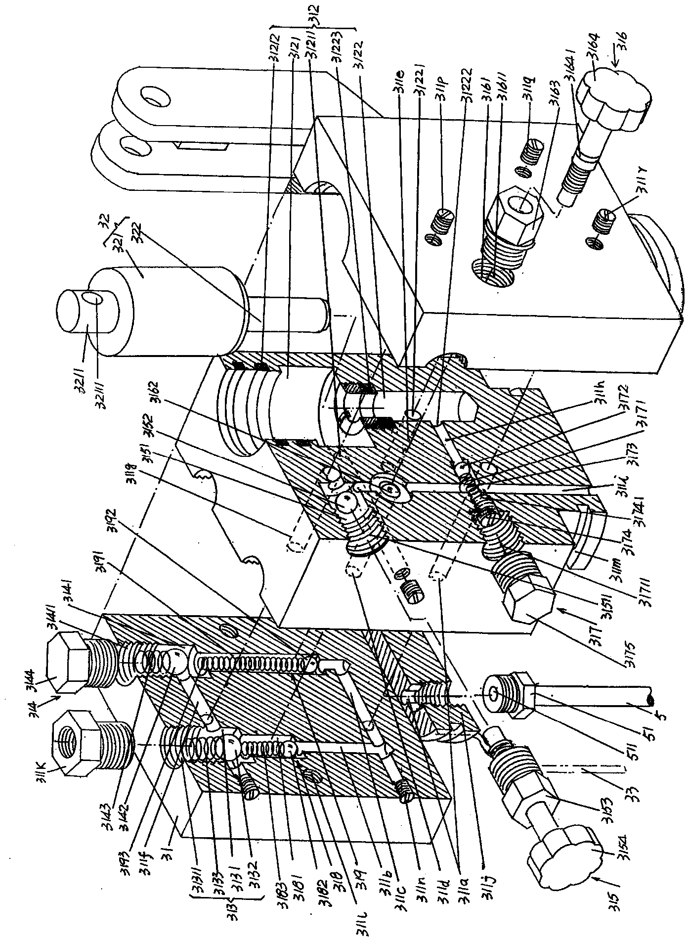
[0052] See Figure 5 , in the present embodiment, the small pump overpressure drain channel 311h is moved toward the direction of the oil return channel 311g of the working cylinder ( Figure 5 The state shown is shifted to the left), and the small pump overpressure oil discharge passage 311h is connected with the small pump inlet and outlet oil passage 311e, and a small pump overpressure valve connected to the small pump overpressure oil discharge passage 311h is set on the valve body 31 The oil return hole 311s of the oil drain channel, the oil return hole 311s of the small pump overpressure oil drain channel communicates with the oil storage tank 33 . Compared with the oil return passage 311i in Embodiment 1, this oil passage structure communicates with the oil return passage 311g of the working oil cylinder, the overpressure oil discharge passage 311h of the small pump, and the fast and slow speed control valve chamber 3161. The oil return passage 311i is only connected to...


PUM


Abstract

The invention relates to a hydraulic power pack structure of a hydraulic press of a jack, and belongs to the field of press machines. The hydraulic press of the jack comprises a rack and an operating cylinder. The hydraulic power pack structure comprises a hydraulic power pack body comprising a valve body, a pump body and an oil storage tank, and is characterized in that the valve body is provided with an oil absorption duct, a big pump oil absorption duct, a small pump oil absorption duct, a big pump oil in-out duct, a small pump oil in-out duct, an oil outlet duct, an operating cylinder oil return duct, a small pump overpressure oil drainage duct, an oil return duct, a pump body cavity, a big pump oil outlet valve, a small pump oil outlet valve, an oil return control valve, a high-low-speed control valve, a pressure regulating valve, a big pump oil absorption valve and a small pump oil absorption valve. When the operating cylinder is in an idle stroke state, big and smaller pump plunger shaft cavities of the valve body simultaneously supply oil to the operating cylinder in a small pressure and big oil mass oil supply way, so the operation efficiency of quick oil pumping is realized; when the operating cylinder is in a loading state, high-pressure and low-speed oil pumping is realized to realize labor-saving operation; the valve body is simple in structure, and the processing is convenient.

Description

technical field [0001] The invention belongs to the field of pressure machinery, and in particular relates to a hydraulic pump station structure of a jack hydraulic press. Background technique [0002] The aforementioned hydraulic pump station structure is a mechanism that provides a power source for the working oil cylinders arranged on the frame of the jack hydraulic press. Compared with large-scale hydraulic presses (also known as hydraulic presses), jack hydraulic presses can play a role in filling gaps. The specific performances are wide adaptability to application sites, small size, convenient operation, and low cost. However, large or medium and small hydraulic presses are the opposite. They need to be equipped with corresponding hydraulic stations, have a large overall volume, poor adaptability to the place of use, high equipment costs, and difficult investment and management. It is precisely because the jack hydraulic press has the aforementioned advantages that ar...

Claims


Application Information

Patent Timeline
IPC IPC(8): F15B11/17
Inventor 石永良王胜陈晓杰严袁
Owner CHANGSHU TONGRUN AUTO REPAIRING EQUIP
Why Eureka
Try Eureka