Heat source flow equilibrium control device and using method thereof

A flow balance and control device technology, applied in heating methods, applications, household heating, etc., can solve the problems of large power consumption of circulating pumps, high procurement costs, and large boiler sizes, so as to save power consumption and reduce noise Pollution, reduce the effect of paving construction

Inactive Publication Date: 2014-09-17
何宗衡
View PDF6 Cites 2 Cited by
  • Summary
  • Abstract
  • Description
  • Claims
  • Application Information

AI Technical Summary

Problems solved by technology

[0003] The present invention provides a heat source flow balance control device and its use method, which overcomes the above-mentioned deficiencies in the prior art, and can effectively solve the problem of centralized power supply of existing large boilers. The power of the circulating pump and boiler required in the thermal mode is large, the purchase cost is high, the power cons

Method used


Image

  • Heat source flow equilibrium control device and using method thereof
  • Heat source flow equilibrium control device and using method thereof
  • Heat source flow equilibrium control device and using method thereof

Examples


Embodiment 1

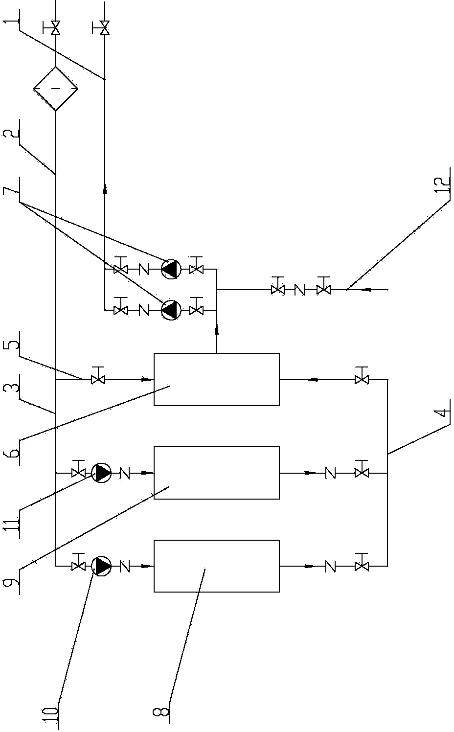
[0053] Embodiment one: as attached figure 1 As shown, the heat source flow balance control device includes a heat source section and a pipeline delivery section, wherein the pipeline delivery section includes a water supply main pipe 1 and a return water main pipe 2, and the heat source section includes a first branch 3, a second branch 4, and a third branch Road 5, energy mixing device 6 and gas boiler, the first branch 3 and the second branch 4 are connected by a gas boiler, the water inlet of the gas boiler is equipped with a boiler circulation pump, and the water outlet of the third branch 5 is connected to the The first water inlet of the mixing device 6 is connected, the end of the return water main pipe 2 is respectively connected with the water inlet of the third branch 5 and the water inlet of the first branch 3, and the water outlet of the second branch 4 is connected with the water mixing device The second water inlet of 6 is connected, and the water outlet of th...

Embodiment 2

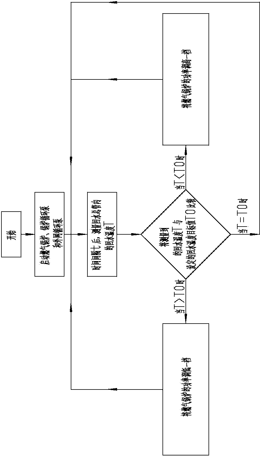
[0060] Embodiment two: as attached figure 1 , 2 As shown, a method of using the above-mentioned heat source flow balance control device is carried out according to the following steps:

[0061] The first step is to start the gas boiler, the boiler circulation pump and the external network circulation pump 7;

[0062] In the second step, after the time interval t, measure the return water temperature T in the return water main pipe 2;

[0063] The third step is to compare the measured return water temperature T with the set return water temperature target value T 0 Compare;

[0064] When T 0 , then increase the power of the gas boiler by one gear, and repeat the second and third steps;

[0065] When T=T 0 , repeat the second and third steps;

[0066] when T>T 0 , turn down the power of the gas boiler by one gear, and repeat the second and third steps.

Embodiment 3

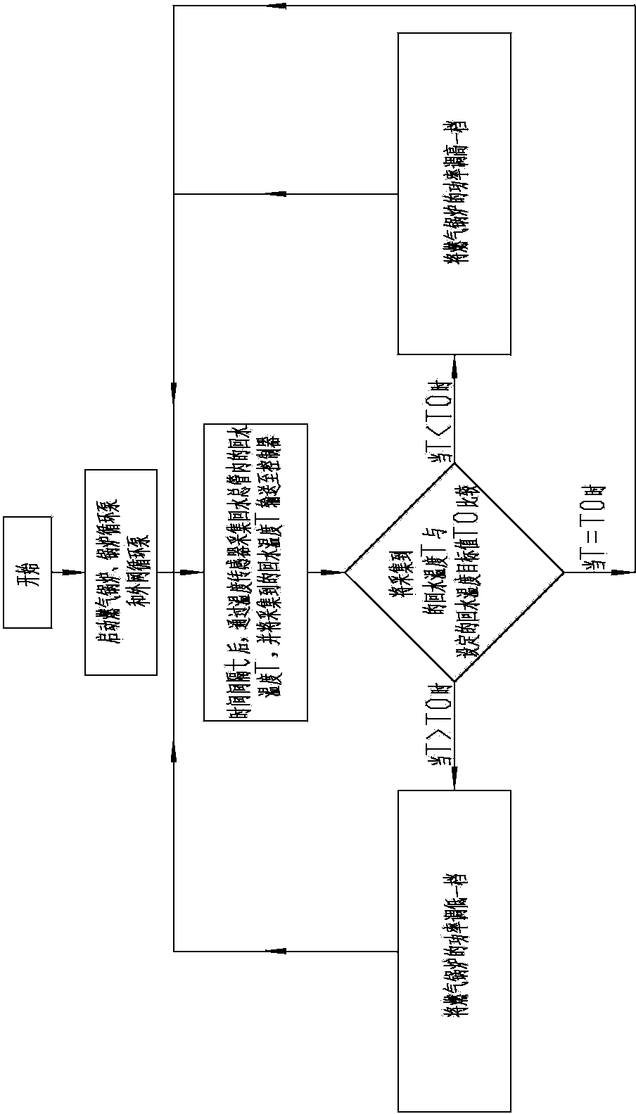
[0067] Embodiment three: as attached figure 1 , 3 As shown, a method of using the above-mentioned heat source flow balance control device is carried out according to the following steps:

[0068] The first step is to start the gas boiler, the boiler circulation pump and the external network circulation pump 7;

[0069] In the first step, after a time interval of t, the return water temperature T in the return water main pipe 2 is collected by the temperature sensor, and the collected return water temperature T is sent to the controller;

[0070] The second step is to compare the collected return water temperature T with the set return water temperature target value T 0 Compare;

[0071] When T 0 , then increase the power of the gas boiler by one gear, and repeat the second and third steps;

[0072] When T=T 0 , repeat the second and third steps;

[0073] when T>T 0 , turn down the power of the gas boiler by one gear, and repeat the secon...


PUM


Abstract

The invention relates to the technical field of heating devices, in particular to a heat source flow equilibrium control device and a using method thereof, wherein the heat source flow equilibrium control device comprises a heat source section and a pipe conveying section, a first branch is connected with a second branch through a gas boiler, the water outlet of a third branch is communicated with a first water inlet of an energy mixing device, the tail end of the water return main pipe is respectively communicated with the water inlet of the third branch and the water inlet of the first branch, the water outlet of the second branch is communicated with a second water inlet of the energy mixing device, and the water outlet of the energy mixing device is communicated with a water supply total pipe through an outer-net circulating pump. The heat source flow equilibrium control device is reasonable and compact in structure and convenient to use, the power of a burner can be controlled in real time according to temperature change and requirements, the labor cost is reduced, the control precision is improved, and the device is more energy-saving and environment-friendly; the power and the size of the gas boiler can be both reduced, the purchase cost of the gas boiler is lowered, the occupied area of the gas boiler is reduced, and the noise generated during work of the gas boiler is reduced.

Description

technical field [0001] The invention relates to the technical field of heat supply device control devices, and relates to a heat source flow balance control device and a method for using the same. Background technique [0002] At present, the central heating in the city mainly uses large boilers as the heat source, and then the heat medium is transmitted to the first-level pumping station and the second-level pumping station through the pipeline, and finally delivered to the user's home through the second-level pumping station or the third-level pumping station. In the single-circulation heating process of this large boiler, the adjustment of the heat supply is realized by adjusting the combustion power of the boiler, that is, the circulation flow rate remains unchanged, and the temperature of the water body is changed. Therefore, no matter how much heat is needed at the hot end, the circulation pump needs to push all the circulating water into the boiler for heating. In thi...

Claims


Application Information

Patent Timeline
IPC IPC(8): F24D3/02F24D3/10F24D19/10
Inventor 何宗衡
Owner 何宗衡
Why Eureka
Try Eureka