
Method for selecting target aiming point on tail section based on convex hull calculation

A technology of convex hull calculation and aiming point, which is applied in calculation, computer parts, image data processing, etc., to achieve the effect of small calculation complexity, strong flexibility and practicability, and fast calculation speed

Inactive Publication Date: 2014-09-17
BEIJING INSTITUTE OF TECHNOLOGYGY
View PDF3 Cites 12 Cited by
  • Summary
  • Abstract
  • Description
  • Claims
  • Application Information

AI Technical Summary

Problems solved by technology

[0005] The purpose of the present invention is to use the method of constructing the convex hull in computational geometry to cover the target area, and at the same time solve the problems of target edge contour extraction and target aiming point selection, and propose a method for selecting the final target aiming point based on convex hull calculation

Method used


Image

  • Method for selecting target aiming point on tail section based on convex hull calculation
  • Method for selecting target aiming point on tail section based on convex hull calculation
  • Method for selecting target aiming point on tail section based on convex hull calculation

Examples


Embodiment 1

[0036] A method for selecting the aiming point of the terminal target based on convex hull calculation is used to realize the real-time and precise selection of the aiming point of the target by the radar detector. Such as figure 1 shown, including the following steps:

[0037] Step 1: Obtain an image of the target through the radar detector.

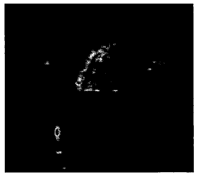
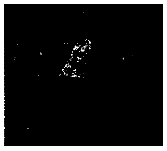
[0038] Step 2: Preprocessing the acquired target image. The processing methods are as follows: use statistical method to filter and denoise the image, use Ostu method to perform threshold segmentation, and use graphics method to open and close the binarized image. Preprocessing results such as figure 2 shown. Next, corner points are extracted from the processed image. The corner point extraction results are as follows image 3 shown.

[0039] Step 3, using the corner point coordinates extracted in Step 2, using a real-time convex hull calculation method to construct a convex polygon.

[0040] Since most of the extracted points ...

Embodiment 2

[0052] A method for selecting the aiming point of the terminal target based on convex hull calculation, which realizes the accurate delivery of relief materials to the disaster area. Include the following steps:

[0053] Step 1. Obtain the topography of the disaster area through the airborne detector, such as Figure 5 shown.

[0054] Step 2. Preprocess the acquired target image to remove interference noise, and then perform corner extraction on the processed image. The result of corner extraction is as follows: Image 6 shown.

[0055] Step 3, using the corner point coordinates extracted in Step 2, using a real-time convex hull calculation method to construct a convex polygon.

[0056] Since most of the extracted points are concentrated in the target area, the convex polygon constructed from these points can cover the target area. The construction method is as follows:

[0057] First, for the corner point coordinate p extracted in step 2 1 (x 1 ,y 1 ),p 2 (x 2 ,y 2...


PUM


Abstract

The invention discloses a method for selecting a target aiming point on a tail section based on the convex hull calculation and belongs to the technical field of target detection. According to the method for selecting the target aiming point on the tail section based on the convex hull calculation, a coverage problem solution in computation geometry is applied to selection of the target detection aiming point, a convex hull is established, the convex hull is a convex polygon with which a target area can be completely covered, and the target aiming point can be determined according to the convex polygon accurately in real time. According to the method for selecting the target aiming point on the tail section based on the convex hull calculation, the convex hull can be updated in real time according to posture change caused by movement of a target, so that the target area is covered, the accurate aiming point is obtained, it is guaranteed that that aiming point is located in the target area, shot missing is avoided, and both the flexibility and the practicability are high. Due to the fact the target area is covered by establishing the convex hull, and template matching and accurate contour extraction are not needed; the method has the advantages that the calculation complexity is low and the calculation speed is high; meanwhile, the requirement for the performance of a detector is lowered.

Description

technical field [0001] The invention relates to a method for selecting a target aiming point, in particular to a real-time and accurate selection method for a target aiming point at the end of detection, and belongs to the technical field of target detection and recognition. Background technique [0002] Aircraft navigation, safe landing at a designated location, and accurate delivery of air-dropped disaster relief supplies all involve detection, identification, and tracking of targets or target areas, and the selection of aiming points needs to be completed accurately in real time to realize the safe landing of the aircraft itself at a fixed point, Target tracking or accurate delivery of materials. Especially at the end of the flight of the aircraft, for the maneuvering target, both the aircraft itself and the target have large attitude changes. As the detector and the target quickly approach, the target image continues to increase, and even overflows the field of view. At ...

Claims


Application Information

Patent Timeline
Patent Type & Authority Applications(China)
IPC IPC(8): G06K9/46G06T5/00
Inventor 王萱邓甲昊刘伟莲
Owner BEIJING INSTITUTE OF TECHNOLOGYGY
Learn More