Gating circuit and gating method of resistive random access memory (RRAM)
A random access memory and resistance conversion technology, applied in the field of memory, can solve the problems of insufficient memory speed index, low resource utilization rate, high power consumption, etc.
- Summary
- Abstract
- Description
- Claims
- Application Information
AI Technical Summary
Problems solved by technology
Method used
Image
Examples
Embodiment 1
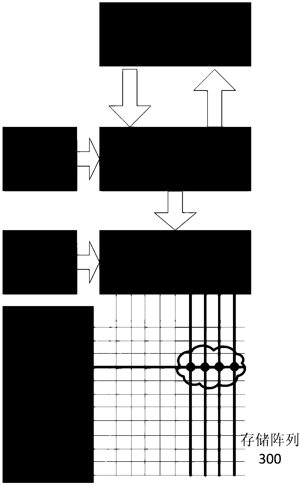
[0029] see image 3 , a gating circuit of a resistance transition random access memory RRAM, comprising: a row decoder 301, a column decoder 302, a first data selector 303 and a second data selector 305; the second data selector 305 is connected to a control signal 304; the control signal includes: a read enable signal and a write enable signal, which are used to select the working mode of the memory, that is, read or write; the second data selector 305 is connected with the first data selector 301 and the RRAM respectively Peripheral circuits 306 are connected to realize data writing and reading of the memory array; wherein, the row decoder 301 receives an external row address signal, sends a row gate signal to the memory array of the RRAM, and gates a row of memory cells; column decoding The device 302 receives an external column address signal, sends a column strobe signal to the first data selector 303, and selects a plurality of columns of memory cells; thus, in the memor...
Embodiment 2
[0039] see Figure 4 , on the basis of Embodiment 1, this embodiment proposes this embodiment for the selection switch and additional structural features; the data selection switch 4031 includes a transmission gate 40311 and an inverter 40312; the control signal terminal of the transmission gate 40311 and the inverter The input terminal of 40312 is connected as the control signal input terminal of data selection switch 4031, and is connected with the output terminal of column decoder 402; the input terminal of transmission gate 40311 is connected with the column line of memory array as the input terminal of data selection switch 4031 ; The output end of the transmission gate 40311 is connected to the second-stage data selector 405 through the data path 404; the output end of the inverter 40312 is connected to the inverting clock of the transmission gate 40311; thereby realizing a stable and efficient gating operation.
Embodiment 3
[0041] Such as Figure 5 As shown, the structure of the resistive memory is basically the same as the structure proposed in the second embodiment; the difference is that the output of the column decoder not only controls one selection switch, but controls n ones at the same time. Moreover, the decoding method of the column decoder is also different from the traditional method, adopting the method of segment decoding and then ANDing.
[0042] Taking the 8-bit data to be decoded as an example, the 8-bit decoded data is divided into bits [0:3] and bits [4:7]. First decode the [0:3] bit data, the result is 2 4 bit, and then decode the [4:7] bit data, the result is 2 4 . Then translate the [0:3] bits to 2 4 bit data respectively and [7:4] bits to translate the 2 4 The bit data is ANDed, and then combined according to the high and low bits, and finally 2 is obtained 8 The bit data is the complete and correct decoding result of the decoder. The input signal of the column decod...
PUM
 Abstract
Description
Claims
Application Information
 - R&D
- Intellectual Property
- Life Sciences
- Materials
- Tech Scout
- Unparalleled Data Quality
- Higher Quality Content
- 60% Fewer Hallucinations
Browse by: Latest US Patents, China's latest patents, Technical Efficacy Thesaurus, Application Domain, Technology Topic, Popular Technical Reports.
© 2025 PatSnap. All rights reserved.Legal|Privacy policy|Modern Slavery Act Transparency Statement|Sitemap|About US| Contact US: help@patsnap.com


