A Quadrature Modulation Receiver Circuit Architecture Based on Injection Locked Ring Oscillator

A ring oscillator, injection locking technology, applied in electrical components, transmission systems, etc., can solve the problems of large circuit occupation area, demodulation errors, high power consumption, etc., to avoid demodulation errors, reduce power consumption, reduce The effect of circuit footprint

Active Publication Date: 2016-04-27
ZHEJIANG UNIV
View PDF3 Cites 0 Cited by
  • Summary
  • Abstract
  • Description
  • Claims
  • Application Information

AI Technical Summary

Problems solved by technology

[0004] In view of this, the purpose of the present invention is to provide a quadrature modulation receiver circuit architecture based on an injection-locked ring oscillator, to overcome the demodulation error and circuit occupation caused by the phase difference between the RF signal and the local oscillator signal in the prior art The problem of large area and high power consumption

Method used


Image

  • A Quadrature Modulation Receiver Circuit Architecture Based on Injection Locked Ring Oscillator
  • A Quadrature Modulation Receiver Circuit Architecture Based on Injection Locked Ring Oscillator
  • A Quadrature Modulation Receiver Circuit Architecture Based on Injection Locked Ring Oscillator

Examples


Embodiment Construction

[0022] The present invention will be described in further detail below in conjunction with the accompanying drawings.

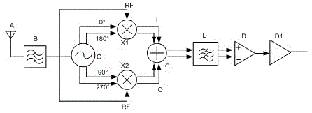
[0023] refer to figure 2 , the quadrature modulation receiver circuit architecture based on the injection-locked ring oscillator of the present invention includes:

[0024] A band-pass filter B, whose input end is connected to the antenna A, and outputs an RF signal;

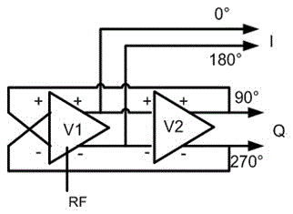
[0025] An injection-locked ring oscillator O, whose input terminal is connected to the output terminal of the band-pass filter B, outputs two paths of differential signals which are mutually orthogonal;

[0026] The two mixers X1 and X2 mix the two quadrature output signals of the injection-locked ring oscillator O with the RF signal respectively, and the first input terminal of the first mixer X1 is in phase with the input-locked ring oscillator O The output terminal is connected, the second input terminal is connected with the output terminal of the bandpass filter B, the first input termi...


PUM


Abstract

The invention discloses an orthogonal modulation receiver circuit structure based on an injection locking ring oscillator. The orthogonal modulation receiver circuit structure comprises an antenna, a band-pass filter, a low-pass filter, the injection locking ring oscillator, two frequency mixers, a signal synthesizer and a comparator. The injection locking ring oscillator is of a two-stage inverter cascading structure, wherein an on-off keyed RF signal is input into the injection locking ring oscillator, and two differential signals which are mutually orthogonal and are the same as the RF signal in frequency are output by the injection locking ring oscillator. The two mixtures are used for mixing the RF signal with an in-phase signal and the orthogonal signals output by the injection locking ring oscillator to obtain two zero-intermediate frequency signals which are mutually orthogonal. The two zero-intermediate frequency signals are synthesized through the signal synthesizer and then demodulated through the comparator. According to the orthogonal modulation receiver circuit structure, power consumption of a circuit can be reduced greatly, the area occupied by the circuit can be reduced, demodulation errors caused by existence of phase differences between the RF signal and the output signals of the oscillator are avoided, demodulation blind spots are eliminated, and no signal loss is caused.

Description

technical field [0001] The present invention relates to the technical field of electronic circuits, and more specifically relates to a quadrature modulation receiver circuit architecture based on an injection-locked ring oscillator. Background technique [0002] At present, when the RF transceiver adopts a zero-IF structure, a fixed oscillator is usually used to generate a local oscillator signal with the same carrier frequency as the RF (radio frequency) signal, and a zero-IF signal is obtained after mixing with the RF signal. However, due to the The frequency of the received RF signal may jitter, so that the signal obtained after frequency mixing is not an ideal zero-IF signal, and the method of using phase-locked loop technology to generate local oscillator signals will generate huge power consumption due to the phase-locked loop circuit . In addition, even if the frequency of the local oscillator signal and the RF signal input by the mixer are the same, the phase differ...

Claims


Application Information

Patent Timeline
Patent Type & Authority Patents(China)
IPC IPC(8): H04B1/16
Inventor 虞小鹏范德章谭年熊
Owner ZHEJIANG UNIV
Why Eureka
Try Eureka