Microbubble water generation method and generation device

The technology of a generating device and a generating method, which is applied in the field of microbubble water generation and generating devices, can solve the problems of small number of microbubbles, waste of water resources, clogging, etc., and achieve long-term reliable work and avoid the effect of clogging

Active Publication Date: 2014-09-24
NINGBO HAIBO PRECISION MACHINERY MFG
View PDF5 Cites 23 Cited by
  • Summary
  • Abstract
  • Description
  • Claims
  • Application Information

AI Technical Summary

Problems solved by technology

[0005] However, it was found during use that because the above-mentioned microbubble water is generated online, that is, water and air (or other gases) are simultaneously input into the dissolved gas tank through a compression pump, the precondition for generating microbubbles is air (or other gases) ) and water should be input in a certain ratio. If air (or other gases) is excessively mixed into the water, the microbubble water flowing out from the shower will form a short-term shock wave due to too many large bubbles, which will cause unstable microbubble water.
If the amount of air (or other gases) mixed into the water is insufficient, the number of microbubbles formed will be small, which will not achieve better cleaning and massaging effects on the h

Method used


Image

  • Microbubble water generation method and generation device
  • Microbubble water generation method and generation device
  • Microbubble water generation method and generation device

Examples


no. 1 example

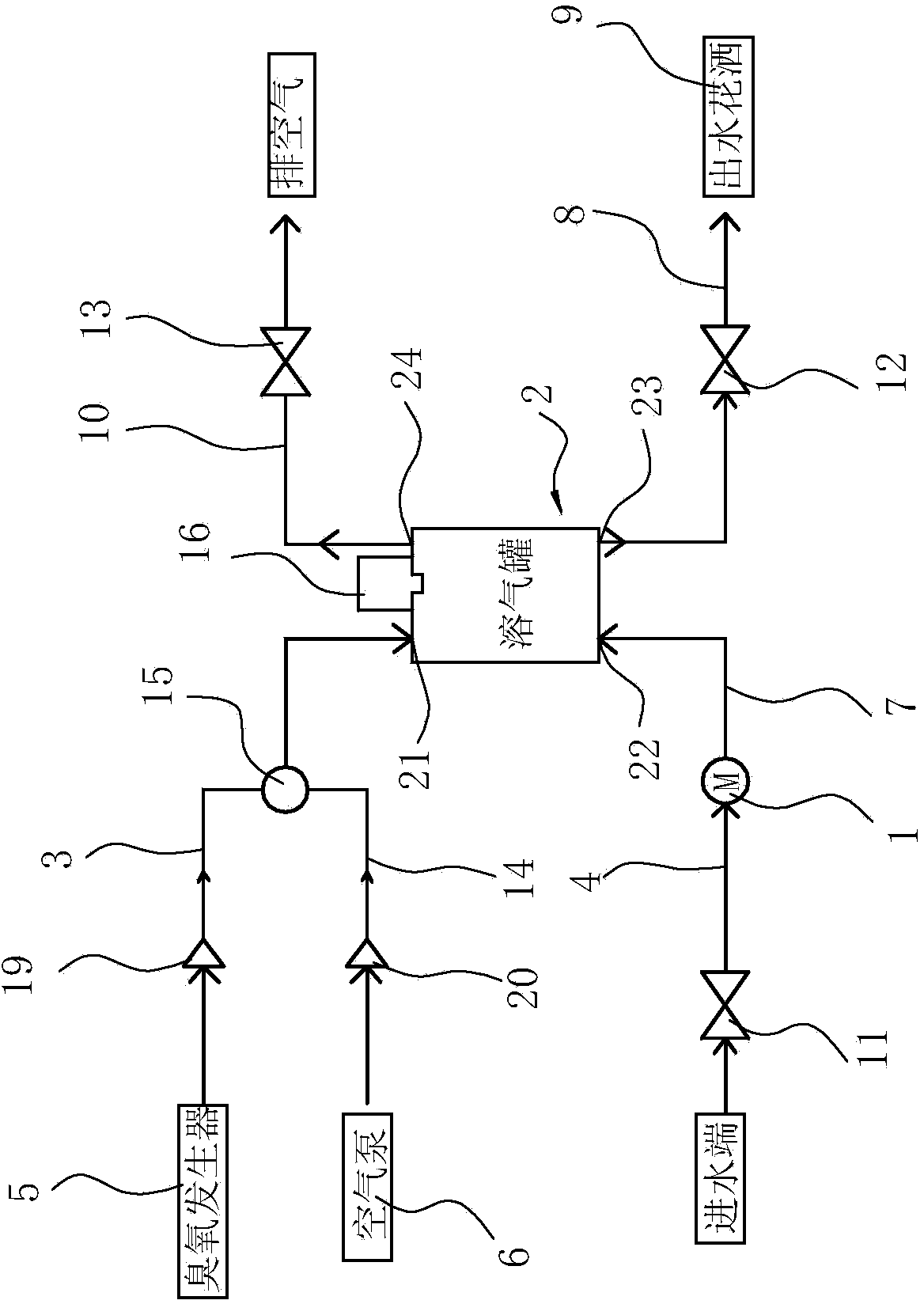
[0043] Such as figure 1 with figure 2 As shown, the microbubble water generating device is to pass a certain amount of ozone in the water, therefore, the delivery source of the gas to be inflated mentioned in the above method is an ozone generator, in order to make purer ozone microbubble water, in the above An "exhaust" step is also added between the ② step and the ③ step of the method. Specifically, the microbubble water generating device includes a compression pump 1, a dissolved air tank 2, an air inlet pipe 3, a water inlet pipe 4, an ozone generator 5 and an air pump 6, wherein the compression pump 1, the dissolved air tank 2, the air pump 6. Installed on the shell of the microbubble water generating device, the dissolved air tank 2 is provided with an air inlet 21, a water inlet 22, a water outlet 23 and an exhaust port 24 for outputting microbubble water, and the air inlet 21 passes through The inlet pipe 3 is connected to the outlet of the ozone generator 5, the wa...

no. 2 example

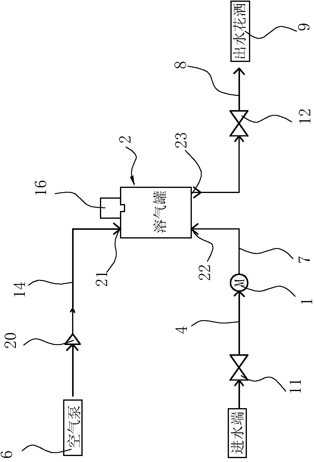
[0055] Such as image 3 with Figure 4 The difference between this microbubble water generating device and the above-mentioned first embodiment is that the air dissolved in the water does not need to exhaust the air in the dissolved air tank before the air intake, that is, there is no need to set up another air tank in the dissolved air tank 2. Exhaust port, exhaust pipe and exhaust solenoid valve, while removing the ozone generator and corresponding pipelines in Embodiment 1, the branch circuit is the intake pipe. The air pump is the delivery source of the gas to be inflated.

[0056] When in use, adopt the following specific methods to produce microbubble water:

[0057] ①. Turn on the power, and the microbubble water generating device is in standby state;

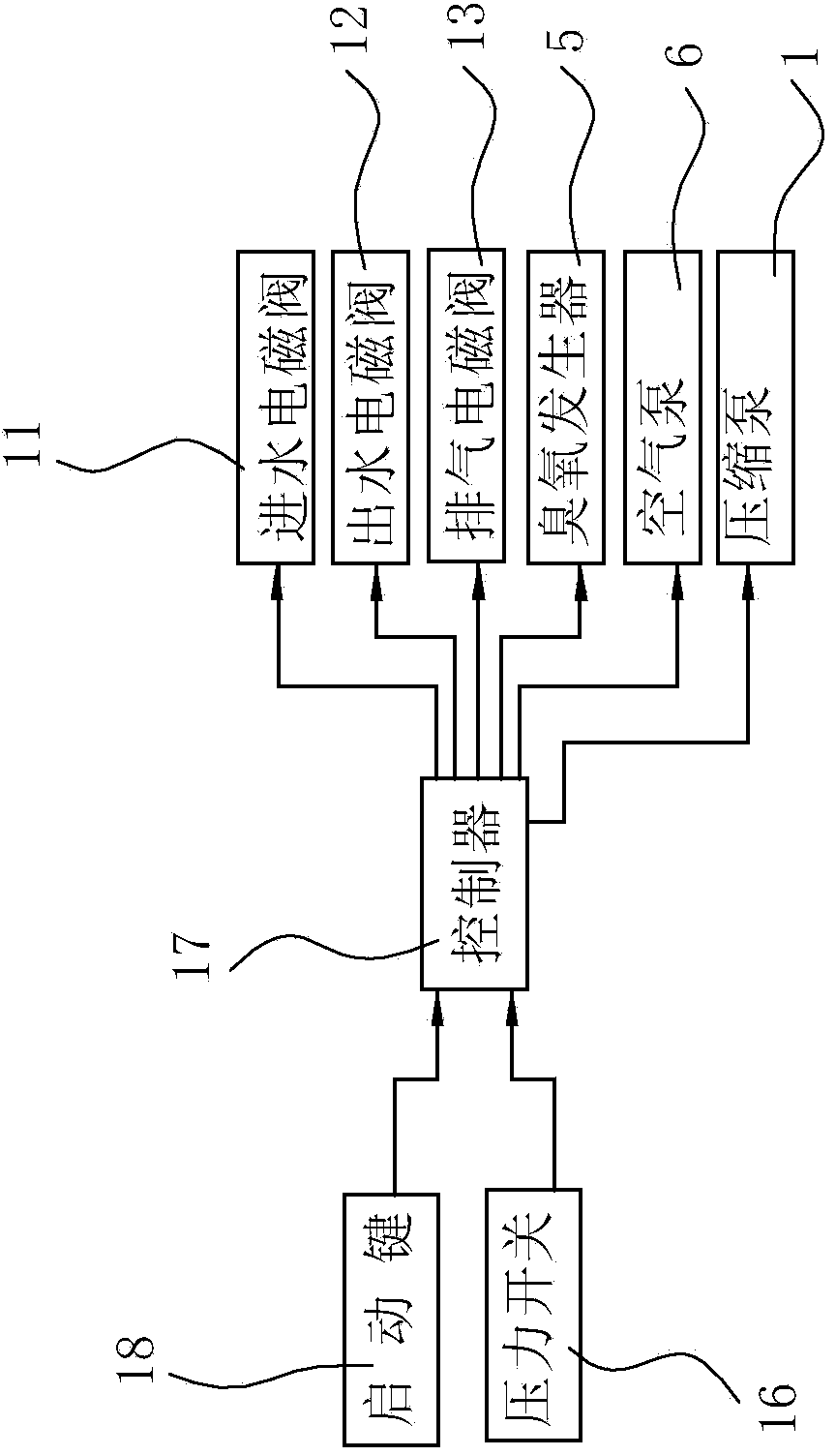
[0058] ②, press the start key 18, at this time the controller sends a signal to the air pump 6, the water inlet solenoid valve 11, and the water outlet solenoid valve 12, so that the water inlet solenoid valve 11, the...

Embodiment 3

[0065] Such as Figure 5 with Figure 6 As shown, the difference between the microbubble water generating device and the above-mentioned first embodiment is: the difference of the drainage mechanism, that is, the air pump 6 and the branch circuit and the second one-way valve 20 in the first embodiment are canceled, and the An air delivery pipe 25 communicating with the water inlet pipe is provided, and an air delivery solenoid valve 26 connected with the input end of the controller is installed on the air delivery pipe 25 .

[0066] During use, the difference between the microbubble water generation method and the method of the above-mentioned first embodiment is: the 6th and 7th steps are different, that is, in the present embodiment:

[0067] ⑥. Compression pump 1 continues to work until the required ratio is reached between the input amount of water and the amount of ozone input into the dissolved air tank before. During specific control, the ratio can be controlled by mic...


PUM


Abstract

The invention relates to a microbubble water generation method and a generation device. The microbubble water generation method comprises the following steps: by pressing down a start key, a to-be-filled gas is imported into a dissolved gas tank from a to-be-filled gas conveying source, and gas is stopped conveying when the input to-be-filled gas reaches the needed amount; then a compression pump starts working, then water is conveyed into the dissolved gas tank until a pressure switch actuates, a controller controls an effluent water electromagnetic valve to switch on, to obtain the prepared microbubble water, then the compression pump continues working and stops working until the needed ratio of the import amount of water to the amount of the imported to-be-filled gas is achieved; and the controller controls a drain mechanism to work, and the microbubble generation device is under standby state until the remaining microbubble water in the dissolved gas tank is drained out. The invention further discloses a microbubble generation device corresponding to the method. By adopting the method and the device, a gas inlet channel is not easily plugged, the defects in the prior art can be avoided, so that the device can reliably work for long time, and the device also has a water-saving function.

Description

technical field [0001] The invention relates to a method and a device for generating microbubble water. Background technique [0002] Microbubble is a general term for bubbles with a diameter of less than 50 μm. When a large number of microbubbles form milk-like water, it is called microbubble water. Existing micro-bubble water generating devices generally include a compression pump (i.e. a high-pressure water pump), a water inlet pipe connected to the inlet of the compression pump, an air dissolving tank connected to the outlet of the compression pump, and an outlet pipe connected to the outlet of the dissolving air pipe. The water pipe, such as the structure disclosed in the Chinese patent application publication number CN102728251AY "Inlet and Outlet Water Module of Microbubble Generator". When the microbubble generator is working normally, start the compression pump. When the compression pump is pumping water, it uses the negative pressure generated to draw the air in t...

Claims


Application Information

Patent Timeline
IPC IPC(8): C02F1/68B01F3/04B01F15/04B01F15/02
Inventor 夏少华孔令杰
Owner NINGBO HAIBO PRECISION MACHINERY MFG
Why Eureka
Try Eureka