Cable reinforcing rib
A technology for reinforcing ribs and cables, applied in the field of reinforcing ribs, can solve the problems that cables cannot meet the requirements of the seabed environment, and achieve the effect of increasing strength and toughness, improving strength and flexibility
- Summary
- Abstract
- Description
- Claims
- Application Information
AI Technical Summary
Problems solved by technology
Method used
Image

Examples
Embodiment 2
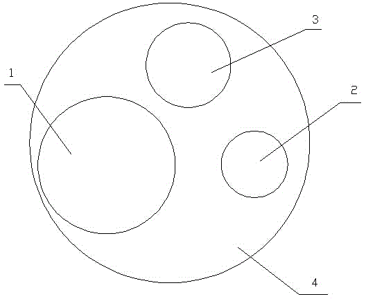
[0033] Such as figure 2 As shown, in this embodiment, including continuous basalt fiber 1, glass fiber 2, carbon fiber 3 and resin matrix 4, continuous basalt fiber 1, glass fiber 2 and carbon fiber 3 are compounded on the resin matrix 4, in weight percentage:
[0034] Continuous Basalt Fiber: 48%
[0035] Glass fiber: 8%
[0036] Carbon fiber: 6%
[0037] Resin matrix: 34%.
[0038] The resin matrix is polyvinyl chloride resin.
[0039] The distribution form of the composite of the continuous basalt fiber, glass fiber and carbon fiber on the resin matrix is: circular distribution
[0040] The specific distribution form of the circular distribution is: the continuous basalt fiber 1 is located at the center of the circle, and the glass fibers 2 and carbon fibers 3 are distributed on the arc at intervals.
Embodiment 3
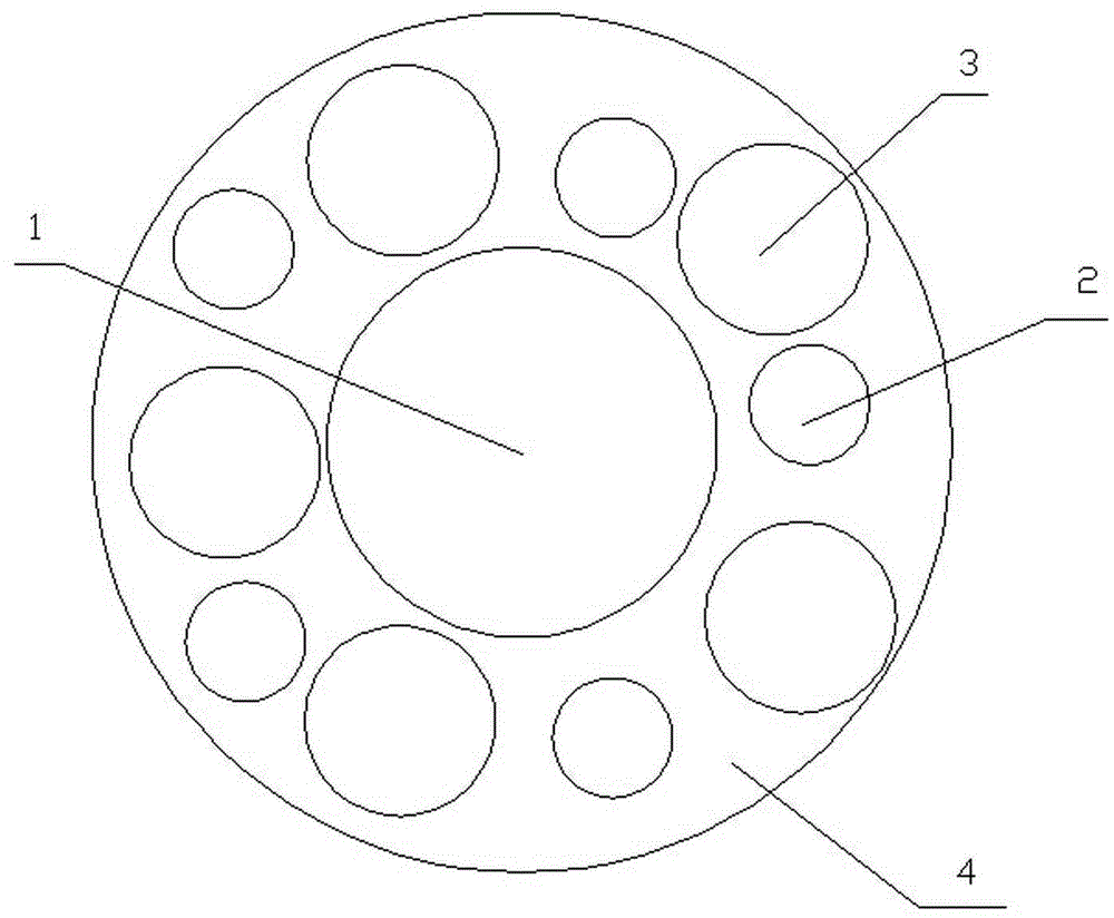
[0042] Such as image 3 As shown, in this embodiment, including continuous basalt fiber 1, glass fiber 2, carbon fiber 3 and resin matrix 4, continuous basalt fiber 1, glass fiber 2 and carbon fiber 3 are compounded on the resin matrix 4, in weight percentage:
[0043] Continuous Basalt Fiber: 40%
[0044] Glass fiber 6%
[0045] Carbon fiber: 8%
[0046] Resin matrix: 46%.
[0047] The resin matrix is a mixed resin of phenolic resin and polyvinyl chloride resin.
[0048] The composite distribution form of the continuous basalt fiber, glass fiber and carbon fiber on the resin matrix is: annular distribution.
[0049] The specific distribution form of the annular distribution is: continuous basalt fiber 1, glass fiber 2 and carbon fiber 3 are distributed in a ring shape, continuous basalt fiber 1 is located in the innermost layer, glass fiber 2 is located in the middle layer, and carbon fiber 3 is located in the outermost layer.
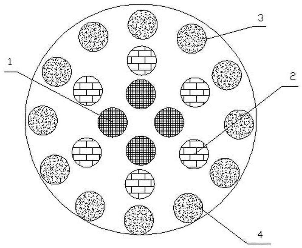
Embodiment 4
[0051] In this embodiment, including continuous basalt fiber 1, glass fiber 2, carbon fiber 3 and resin matrix 4, continuous basalt fiber 1, glass fiber 2 and carbon fiber 3 are compounded on the resin matrix 4, by weight percentage:
[0052] Continuous Basalt Fiber: 42%
[0053] Glass fiber: 7%
[0054] Carbon fiber: 12%
[0055] Resin matrix: 39%.
[0056] The resin matrix is a mixed resin of phenolic resin and polyvinyl chloride resin.
[0057] The composite distribution form of the continuous basalt fiber, glass fiber and carbon fiber on the resin matrix is: annular distribution.
[0058] The specific distribution form of the annular distribution is: continuous basalt fiber 1, glass fiber 2 and carbon fiber 3 are distributed in a ring shape, continuous basalt fiber 1 is located in the innermost layer, glass fiber 2 is located in the middle layer, and carbon fiber 3 is located in the outermost layer.
PUM
 Abstract
Description
Claims
Application Information
 - Generate Ideas
- Intellectual Property
- Life Sciences
- Materials
- Tech Scout
- Unparalleled Data Quality
- Higher Quality Content
- 60% Fewer Hallucinations
Browse by: Latest US Patents, China's latest patents, Technical Efficacy Thesaurus, Application Domain, Technology Topic, Popular Technical Reports.
© 2025 PatSnap. All rights reserved.Legal|Privacy policy|Modern Slavery Act Transparency Statement|Sitemap|About US| Contact US: help@patsnap.com