Digital generator system

A digital generator and generator technology, applied in the direction of electrical automatic control, automatic control, automatic control, etc., can solve the problems of digital generator noise, fuel consumption and emission pollution restrictions under working conditions.

Inactive Publication Date: 2014-09-24
LANGFANG JINRUN TECH
View PDF6 Cites 2 Cited by
  • Summary
  • Abstract
  • Description
  • Claims
  • Application Information

AI Technical Summary

Problems solved by technology

[0004] In view of the above-mentioned problems in the prior art, the technical problem to be solved by the present invention is how to ensure that the digital generator can limit the noise, fuel consumption and working condition emission pollution of the digital generator to the lowest level under different loads and different speeds.

Method used


Image

  • Digital generator system
  • Digital generator system
  • Digital generator system

Examples


Embodiment 1

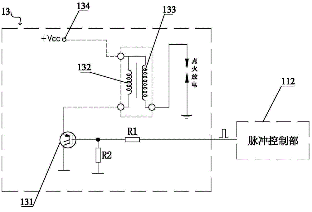
[0023] figure 2 It is a circuit diagram of the digital ignition control part of the first embodiment of the present invention. Such as figure 2 As shown, the digital generator system of this embodiment adopts a transistor-type digital ignition control part, and the digital ignition control part 13 includes: a first switching device 131, a first ignition primary coil 132, a first ignition secondary coil 133, and A power supply 134 for energizing the first ignition primary coil 132 . The first switching device 131 can be a Darlington tube or an IGBT tube, connected between the pulse control part 112 and the first ignition primary coil 132, and the first switching device 131 realizes on / off according to the first pulse signal, when When the first pulse signal is at a high level, the first switch device 131 is turned on; when the first pulse signal is at a low level, the first switch device 131 is turned off. The first ignition primary coil 132 generates electromagnetic induc...

Embodiment 2

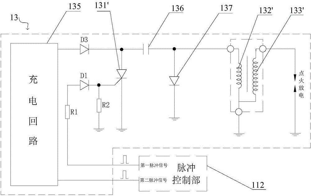
[0026] image 3 It is a circuit diagram of the digital ignition control part of the second embodiment of the present invention. Such as image 3As shown, the digital generator system of this embodiment adopts a capacitive digital ignition control part, and the digital ignition control part 13 includes: a charging circuit 135, a second switching device 131', an ignition capacitor 136, a second ignition primary coil 132', a first Two ignition secondary coils 133 ′ and a first diode 137 . The charging circuit 135 is connected between the pulse control unit 112 and one end of the ignition capacitor 136 to charge the ignition capacitor 136 , and the pulse control unit 112 controls the charging circuit 135 to charge the ignition capacitor 136 by sending out a second pulse signal. The second switching device 131' can be a silicon-controlled rectifier element, connected between the pulse control part 112 and the one end of the ignition capacitor 136, and realizes on / off according to...

Embodiment 3

[0029] Figure 4 It is a circuit diagram of the digital ignition control part of the third embodiment of the present invention. Such as Figure 4 As shown, the digital generator system of this embodiment adopts a capacitive digital ignition control part, and the digital ignition control part 13 includes: a charging circuit 135, a second switching device 131', an ignition capacitor 136, a second ignition primary coil 132', a first Two ignition secondary coils 133' and a second diode 137'. The charging circuit 135 is connected between the pulse control unit 112 and one end of the ignition capacitor 136 to charge the ignition capacitor 136 , and the pulse control unit 112 controls the charging circuit 135 to charge the ignition capacitor 136 by sending out a second pulse signal. The second switching device 131' can be a silicon-controlled rectifier element, connected between the pulse control part 112 and the one end of the ignition capacitor 136, and realizes on / off according ...


PUM


Abstract

The invention provides a digital generator system. The digital generator system comprises a central processor and a digital ignition control part, wherein the central processor comprises a speed collection part for collecting the real-time rotating speed of an original generator of the digital generator system; the digital ignition control part is connected with the central processor and is used for igniting the original generator; the central processor further comprises a pulse control part; the pulse control part is used for sending out a first pulse signal to the digital ignition control part at corresponding ignition time according to the collected real-time rotating speed and according to the corresponding relation table of the pre-stored real-time rotating speed and the ignition time so as to start the digital ignition control part to ignite and discharge a spark plug of the original generator, and thus the ignition advance angle of the original generator is controlled. According to the digital generator system, the optimal power can be obtained in time under the conditions of different loads and different rotating speeds by the original generator of the digital generator system, and the noise, oil consumption and working condition discharge pollutant of the generator can also be restricted to the lowest level.

Description

technical field [0001] The invention relates to a digital generator system, in particular to a digital generator system with a digital ignition function which can still ensure that the digital generator works at its optimum power point when the load and speed of the digital generator change. Background technique [0002] Digital generator is a new generator product field developed in recent years, and the popularization of this product mainly focuses on small generator systems below 5 kilowatts. The alternator of the digital generator set is directly combined with the engine. Compared with the traditional generator set, the size and weight of the digital generator set are reduced by 50%, which makes it applicable to many entertainment occasions and small portable electric tools. It is a real mini power plant. The key component of the digital generator is its built-in microprocessor. With the powerful modular design, it will process and purify the raw power generated by the ...

Claims


Application Information

Patent Timeline
Patent Type & Authority Applications(China)
IPC IPC(8): F02P5/15
Inventor 李宏超张红亮
Owner LANGFANG JINRUN TECH
Why Eureka
Try Eureka