
An air compressor waste heat recovery device and its control method

A waste heat recovery and air compressor technology, applied in heat pumps, refrigerators, refrigeration components, etc., can solve the problems of low utilization rate of waste heat, low comprehensive utilization rate of design, hot gas and hot oil, etc., and achieve high efficiency utilization and high efficiency The effect of heat exchange

Active Publication Date: 2016-09-07
ZHEJIANG UNIV
View PDF16 Cites 0 Cited by
  • Summary
  • Abstract
  • Description
  • Claims
  • Application Information

AI Technical Summary

Problems solved by technology

However, in this patent document, both the oil pipe and the air pipe are connected to the heat energy converter, and the device does not design a heat exchange device suitable for hot gas and hot oil according to the different media in the oil pipe and air pipe, and the comprehensive utilization rate of hot air and hot oil is low; the patent The literature does not set up a corresponding device to monitor whether the utilization device is leaking oil, etc., and the hot oil will emulsify when the temperature is low. If there is no corresponding device to monitor, etc., it will even affect the work of the main body of the air compressor
[0006] Most of the existing air compressor waste heat recovery and utilization devices have low intelligence level and low waste heat utilization rate. How to make the most efficient use of the waste heat of hot air and hot oil while ensuring the normal operation of the air compressor is the direction of current research

Method used


Image

  • An air compressor waste heat recovery device and its control method
  • An air compressor waste heat recovery device and its control method
  • An air compressor waste heat recovery device and its control method

Examples


Embodiment Construction

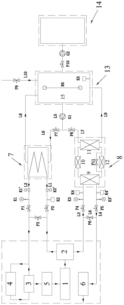
[0067] Such as figure 1 As shown, an air compressor waste heat recovery device includes:

[0068] air compressor 1;

[0069] The oil-gas separator 2, the inlet is connected with the air outlet of the air compressor;

[0070] Bypass valve 3, the inlet is connected with the oil outlet of oil-gas separator 2;

[0071] The oil cooler 4 is connected in parallel at both ends of the bypass valve;

[0072] Air cooler 6, the inlet is connected with the gas outlet of the oil-gas separator;

[0073] The oil filter 5 is connected between the outlet of the bypass valve 3 and the oil return port of the air compressor 1;

[0074] It also includes: an oil circuit electric valve P3 arranged between the oil outlet of the oil-air separator 2 and the inlet of the bypass valve 3; a heat exchange module 7 connected in parallel at both ends of the oil-air electric valve P3; The gas path electric valve P6 between the air outlet of the air cooler and the inlet of the air cooler 6; the enhanced he...


PUM


Abstract

The invention discloses a waste heat recovery device of an air compressor and a control method of the waste heat recovery device. The waste heat recovery device comprises heat exchanging modules and enhanced heat exchanging modules, wherein the heat exchanging modules are arranged in parallel at the two ends of an oil-channel electric valve; the reinforcing heat exchanging modules are arranged in parallel at the two ends of the air-channel electric valve; the heat exchanging modules and the reinforcing heat exchanging modules are utilized to recover and store the heat energy in circulating oil and the heat energy in compressed air lost and wasted when the air compressor operates; the heat energy of the compressed air can be recycled at highest efficiency under the premise that the operation of the air compressor is not impacted. According to the waste heat recovery device of the air compressor and the control method of the waste heat recovery device, the collected data are analyzed and operated so as to realized effective high intelligent control; not only is the efficiency of the operation of the air compressor improved, but also the energy input of the heat energy utilizing modules can be reduced, the energy consumption or fuels for heating are lowered, and energy comprehensive utilizing degree is improved. Therefore, the waste heat recovery device has the advantages that the energy-saving effect is good, the intelligent degree is high, and the stability is excellent.

Description

technical field [0001] The invention relates to the technical field of waste heat recovery and comprehensive utilization, in particular to an air compressor waste heat recovery and utilization device and a control method thereof. Background technique [0002] Air compressors are the main power equipment of most manufacturing enterprises, and all of them have relatively large energy consumption. The compressor of the air compressor is driven by a motor to rotate at high speed, a large amount of air is compressed into the air compressor, the air is compressed under high pressure, and part of the mechanical energy is converted into the potential energy of air molecules, causing the temperature to rise suddenly; the high-speed rotation of the compressor The heat will increase the temperature of the air compressor lubricating oil. The heat of these high-pressure and high-temperature oil-gas mixtures is lost to the air through the cooler of the air compressor after oil-gas separa...

Claims


Application Information

Patent Timeline
Patent Type & Authority Patents(China)
IPC IPC(8): F24H7/02F24H9/20F25B30/06F25B49/02F04B39/00
Inventor 葛俊旭童水光余承霖
Owner ZHEJIANG UNIV
Learn More