
Outer-of-face deformation fatigue test loading device for web gap at position of steel bridge horizontal gusset plates

A fatigue test and loading device technology, applied in the direction of applying repetitive force/pulse force to test the strength of materials, etc., can solve the problem of difficult to reflect the external deformation and force of horizontal gusset plate, model manufacturing, installation time-consuming and laborious, segmental Due to the large size of the test piece, the results of the fatigue test are accurate, easy to disassemble, and highly replaceable.

Active Publication Date: 2014-09-24
CHANGAN UNIV
View PDF5 Cites 7 Cited by
  • Summary
  • Abstract
  • Description
  • Claims
  • Application Information

AI Technical Summary

Problems solved by technology

At present, there are many tests on the fatigue performance of orthotropic steel bridge decks, and the commonly used testing techniques have the following deficiencies: (1) The traditional tests on the fatigue mechanism and maintenance and reinforcement methods of steel bridges use large-segment steel beams for testing , model manufacturing and installation are time-consuming and labor-intensive, and the cost is high, it is difficult to realize a large number of variable parameter test research on fatigue details; The force and deformation of the real bridge require a high loading tonnage, and the fatigue test is expensive
However, at present, no one has conducted a large number of variable parameter tests on the fatigue details of the web gap of the horizontal gusset plate of the steel bridge. Moreover, the current loading device for testing the fatigue performance of the steel bridge is difficult to reflect the web gap of the horizontal gusset plate. The actual out-of-plane deformation and stress

Method used


Image

  • Outer-of-face deformation fatigue test loading device for web gap at position of steel bridge horizontal gusset plates
  • Outer-of-face deformation fatigue test loading device for web gap at position of steel bridge horizontal gusset plates
  • Outer-of-face deformation fatigue test loading device for web gap at position of steel bridge horizontal gusset plates

Examples


Embodiment 1

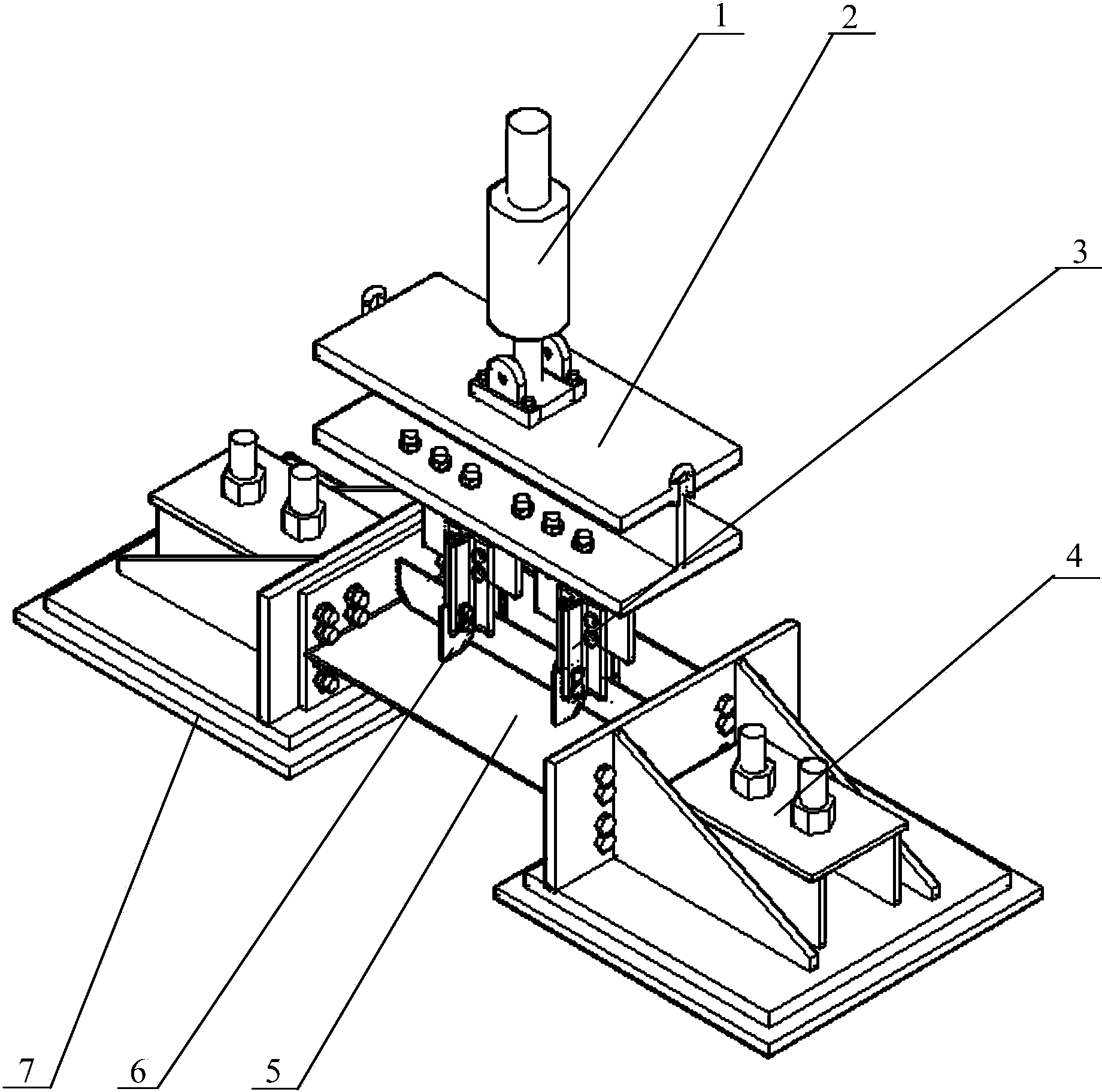
[0028] Such as figure 1 As shown, the loading device for out-of-plane deformation fatigue test of the web gap at the steel bridge horizontal gusset plate of this embodiment is composed of a servo-hydraulic actuator 1, a loading beam 2, a connection assembly 3, a ground anchor 4, and a force-transmitting horizontal gusset plate. 6 and 7 concrete leveling layer.

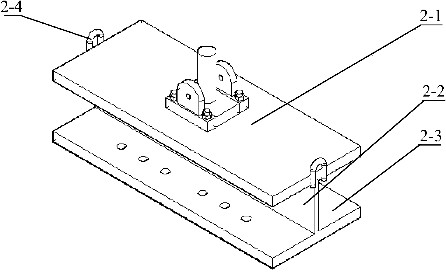
[0029] The loading beam 2 of this embodiment is an I-shaped beam welded from steel plates, see figure 2 The upper flange 2-1 is a rectangular steel plate with a width of 400mm, a thickness of 40mm, and a length of 1000mm. The load beam web 2-2 is a rectangular steel plate with a width of 200mm, a thickness of 20mm, and a length of 1000mm. The lower wing The edge plate 2-3 is a rectangular steel plate with a width of 400 mm, a thickness of 40 mm, and a length of 1000 mm. It has the same geometry and dimensions as the upper flange plate 2-1 and is symmetrical with respect to the load beam web 2-2. In order to temporarily f...

Embodiment 2

[0038] The upper flange plate 2-1 of the loading beam 2 in this embodiment is a rectangular steel plate with a width of 250 mm, a thickness of 16 mm, and a length of 500 mm. The load beam web 2-2 is a width of 100 mm, a thickness of 12 mm, and a length of 500 mm. Rectangular steel plate, the lower flange plate 2-3 is a rectangular steel plate with a width of 250mm, a thickness of 16mm and a length of 500mm.

[0039] The horizontal top plate of the steel anchor box 4-1 of this embodiment is a rectangular plate with a width of 250 mm, a thickness of 18 mm, and a length of 300 mm, and the vertical wing plate is a rectangular plate with a width of 150 mm, a thickness of 16 mmm, and a length of 400 mm.

[0040] In this embodiment, the port where the force-transmitting horizontal gusset plate 6 is connected to the stiffener and the web is processed with an isosceles triangle through welding hole with a right-angle side of 20 mm.

[0041] The other components and their connection relationsh...

Embodiment 3

[0043] The upper flange plate 2-1 of the loading beam 2 of this embodiment is a rectangular steel plate with a width of 550mm, a thickness of 60mm and a length of 1500mm. The web 2-2 of the loading beam is a width of 500mm, a thickness of 24mm, and a length of 1500mm. Rectangular steel plate, the lower flange plate 2-3 is a rectangular steel plate with a width of 550mm, a thickness of 60mm, and a length of 1500mm.

[0044] The horizontal top plate of the steel anchor box 4-1 of this embodiment is a rectangular plate with a width of 400 mm, a thickness of 24 mm, and a length of 800 mm, and the vertical wing plate is a rectangular plate with a width of 450 mm, a thickness of 22 mmm, and a length of 600 mm.

[0045] The port where the force-transmitting horizontal gusset plate 6 is connected to the stiffener and the web is processed with an isosceles right-angled triangle through-welding hole with a right-angle side of 80 mm.

[0046] The other components and their connection relationsh...


PUM

PropertyMeasurementUnit
widthaaaaaaaaaa
thicknessaaaaaaaaaa
lengthaaaaaaaaaa

Abstract

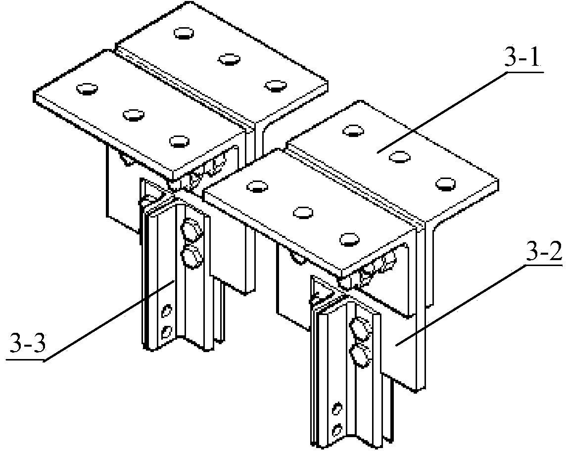
The invention relates to an outer-of-face deformation fatigue test loading device for a web gap at the position of steel bridge horizontal gusset plates. The outer-of-face deformation fatigue test loading device is characterized in that two opposite concrete leveling layers are provided with ground anchors for fixing a tested piece respectively, the two force-transmission horizontal gusset plates are arranged on the tested piece in parallel and connected with a loading beam through connecting assemblies, the loading beam is an I-shaped beam, and a servo hydraulic actuator is connected to the middle of an upper flange plate of the loading beam. According to the outer-of-face deformation fatigue test loading device, the tested piece is fixed to the ground anchors through high-strength bolts, the servo hydraulic actuator provides two concentrated cyclic loads for the force-transmission horizontal gusset plates through the loading beam and the connecting assemblies, the true stress of the position of the web gap of the tested piece at the position of the horizontal gusset plates is simulated, and the fatigue testing result is accurate; due to the fact that the scale of the tested piece is reasonably simplified and reduced, testing space is saved, and the requirement for the loading tonnage is lowered; in addition, the tested piece is high in replaceability and easy to disassemble, a large number of tests for variable parameters can be conveniently and economically carried out, and the application prospects are broad.

Description

Technical field [0001] The invention belongs to the technical field of bridge engineering, and particularly relates to the technical field of bridge engineering test, in particular to a load device for fatigue test of the outer deformation of the web gap surface at the horizontal gusset plate of a steel bridge. Background technique [0002] The fatigue problem of steel bridges seriously affects the service life of the bridge. Research has shown that about 90% of fatigue cracking problems in steel bridges are caused by out-of-plane deformation or secondary stress in fatigue-sensitive details. In the design of steel bridges, flat joints are needed to realize the transverse connection between the steel main beams. The parallel connection is welded or bolted to the horizontal gusset plate of each steel main girder. The horizontal gusset plate is usually welded to the web, and is welded or not connected to the vertical stiffener of the web. In order to avoid fatigue failure of the we...

Claims


Application Information

Patent Timeline
Patent Type & Authority Applications(China)
IPC IPC(8): G01N3/36
Inventor 王春生孙宇佳王茜段兰魏孟春刘喆
Owner CHANGAN UNIV
Learn More