Sand adding device and sand adding method for foam pipe flow
A technology of foam and pipe flow, which is applied in the direction of educational appliances, instruments, teaching models, etc., can solve the problems of not being able to control the sand ratio in real time, the sand particles cannot flow out, and the sand ratio is large, so as to achieve convenient and fast opening and closing, and prevent liquid leakage , the effect of simple operation
- Summary
- Abstract
- Description
- Claims
- Application Information
AI Technical Summary
Problems solved by technology
Method used
Image
Examples
Embodiment 1
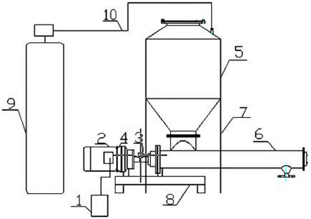
[0033] The present invention relates to a sand adding device for foam pipe flow, the sand adding device comprises a sand adding tank 5, a support frame 7, a motor 2, a coupling 3, a conveyor 6, a valve device, and a frame 8. The top of the sand filling tank 5 is provided with a sand filling port, and the bottom is connected to the conveyor 6 through a flange device 11, and one end of the conveyor 6 is connected to the motor 2 through a coupling 3, and under the action of the motor 2, the sand filling tank 5 The sand body flows into the experimental pipe section through the conveyor 6, the other end of the conveyor 6 is provided with a valve device, the support frame 7 is used to support the sand adding tank 5, and the frame 8 is used to support the whole sand adding device, so The sand adding device also includes a high-pressure gas source 9, which is connected to the sand tank 5 through a connecting pipe 10, and the working pressure of the high-pressure gas source 9 is 3MPa; ...
Embodiment 2
[0036] According to the sand adding device described in Embodiment 1, the difference is that the sand adding device also includes a frequency converter 1 and a reducer 4, the frequency converter 1 is connected to the motor 2, and the motor 2 and the coupling A reducer 4 is connected between the shafts 3;
[0037] The advantage of the design here is that the frequency converter 1 changes the frequency of the motor 2 by changing the frequency of the three-phase alternating current, and then changes the speed of the conveyor 6 through the reducer 4 to adjust the flow rate of the sand body, thereby achieving the purpose of real-time control of sand ratio.
Embodiment 3
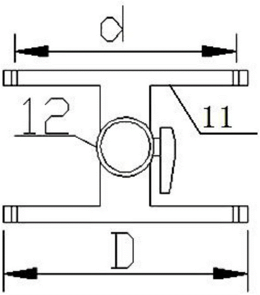
[0039] According to the sand adding device described in Embodiment 1, the difference is that the valve device includes two flange devices 11 and a spherical valve 12, and the spherical valve 12 is connected between the two flange devices 11 , the flange device 11 is detachable, and can be processed into flange diameters D of different sizes according to the diameter of the experimental pipe section. The angle of the flange device 11 is adjustable, and the internal middle position of the flange device 11 is A sealing gasket is added, and the connection between the flange device 11 and the conveyor 6 is sealed by a raw material belt;
[0040] The advantage of the design here is that the valve device ensures that the liquid does not pour back at the beginning of the experiment; the connection between the flange device 11 and the conveyor 6 is sealed by a raw material belt, which is convenient for connection with the test pipe section and effectively prevents liquid leakage; the sp...
PUM
 Abstract
Description
Claims
Application Information
 - R&D
- Intellectual Property
- Life Sciences
- Materials
- Tech Scout
- Unparalleled Data Quality
- Higher Quality Content
- 60% Fewer Hallucinations
Browse by: Latest US Patents, China's latest patents, Technical Efficacy Thesaurus, Application Domain, Technology Topic, Popular Technical Reports.
© 2025 PatSnap. All rights reserved.Legal|Privacy policy|Modern Slavery Act Transparency Statement|Sitemap|About US| Contact US: help@patsnap.com


