Grid drive circuit with self-compensation function

A gate drive circuit and gate technology, applied in the liquid crystal field, can solve the problems of increasing the off-state leakage current of thin film transistors, and achieve the effects of saving design space, reducing overall power consumption, and improving reliability

Active Publication Date: 2014-09-24
TCL CHINA STAR OPTOELECTRONICS TECH CO LTD
View PDF5 Cites 31 Cited by
  • Summary
  • Abstract
  • Description
  • Claims
  • Application Information

AI Technical Summary

Problems solved by technology

The usual design approach is to increase the size of these four thin film transistors. However, increasing the size of the thin film transistors will also increase the off-state leakage current of the thin film transistors, which cannot fundamentally solve the problem.

Method used


Image

  • Grid drive circuit with self-compensation function
  • Grid drive circuit with self-compensation function
  • Grid drive circuit with self-compensation function

Examples


Embodiment Construction

[0040] In order to further illustrate the technical means adopted by the present invention and its effects, the following describes in detail in conjunction with preferred embodiments of the present invention and accompanying drawings.

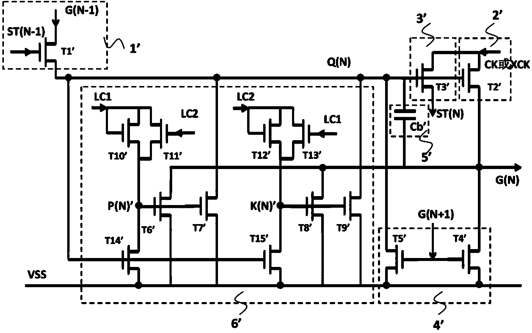
[0041] see image 3 , is a schematic diagram of a single-stage architecture of a gate drive circuit with a self-compensation function in the present invention. Including: a plurality of cascaded GOA units, charging the Nth level horizontal scan line G(N) in the display area according to the control of the Nth level GOA unit, the Nth level GOA unit includes: pull-up control module 1, pull-up module 2 , the downlink module 3, the first pull-down module 4, the bootstrap capacitor module 5, and the pull-down maintenance module 6; the pull-up module 2, the first pull-down module 4, the bootstrap capacitor module 5, and the pull-down maintenance circuit 6 are respectively It is electrically connected to the Nth level gate signal point Q(N) and the ...


PUM


Abstract

The invention provides a grid drive circuit with the self-compensation function. The grid drive circuit comprises a plurality of cascaded grid driver on array (GOA) units. The Nth grade of GOA unit comprises an upward-pull control module, an upward-pull module, a downward-transfer module, a first downward-pull module, a bootstrap capacitor module and a downward-pull maintaining module; the upward-pull module, the first downward-pull module, the bootstrap capacitor module and the downward-pull maintaining module are electrically connected with the Nth grade grid signal point Q(N) and the Nth grade horizontal scanning line G(N), the upward-pull control module and the downward-transfer module are electrically connected with the Nth grade grid signal point Q(N), and the first direct-current low voltage VSS1 and the second direct-current low voltage VSS2 are input into the downward-pull maintaining module. Due to the design of the downward-pull maintaining module with the self-compensation function, reliability of long-term operation of the grid drive circuit is improved; moreover, the design of the downward-pull maintaining module directly controlled by a set of direct-current signal source DC can be adopted for the grid drive circuit with the self-compensation function, and therefore not only can circuit layout design space be saved, but also the overall power consumption of the circuit can be reduced.

Description

technical field [0001] The invention relates to the field of liquid crystal technology, in particular to a gate drive circuit with self-compensation function. Background technique [0002] GOA (Gate Driver on Array, array substrate row drive) technology is to integrate the TFT (Thin Film Transistor, Thin Film Field Effect Transistor) as the gate switch circuit on the array substrate, thereby saving the gate originally arranged outside the array substrate. Drive the integrated circuit part to reduce the cost of the product from two aspects of material cost and process steps. GOA technology is currently a gate drive circuit technology commonly used in the field of TFT-LCD (Thin Film Transistor-Liquid Crystal Display, Thin Film Field Effect Transistor Liquid Crystal Display) technology. Its manufacturing process is simple and has a good application prospect. The functions of the GOA circuit mainly include: using the high-level signal output by the previous row of gate lines to...

Claims


Application Information

Patent Timeline
Patent Type & Authority Applications(China)
IPC IPC(8): G09G3/36
CPCG09G3/3677G11C19/184G11C19/28G09G2310/0286G09G2320/043G02F1/1362G09G3/3648G09G2300/04G09G2330/02G09G2310/08G09G2320/0214G09G2230/00G09G3/36
Inventor 戴超
Owner TCL CHINA STAR OPTOELECTRONICS TECH CO LTD
Why Eureka
Try Eureka