Radio frequency module forming method

A radio frequency module and radio frequency integrated chip technology, applied in the field of radio frequency identification, can solve the problems of large area occupied by radio frequency modules and low production efficiency, and achieve the effect of improving integration, saving production costs, and realizing mass production.

Active Publication Date: 2014-09-24
NANTONG FUJITSU MICROELECTRONICS
View PDF3 Cites 1 Cited by
  • Summary
  • Abstract
  • Description
  • Claims
  • Application Information

AI Technical Summary

Problems solved by technology

[0006] However, the radio frequency module formed by the prior

Method used


Image

  • Radio frequency module forming method
  • Radio frequency module forming method
  • Radio frequency module forming method

Examples


Embodiment Construction

[0027] As mentioned in the background, the radio frequency module formed in the prior art occupies a relatively large area and has low manufacturing efficiency.

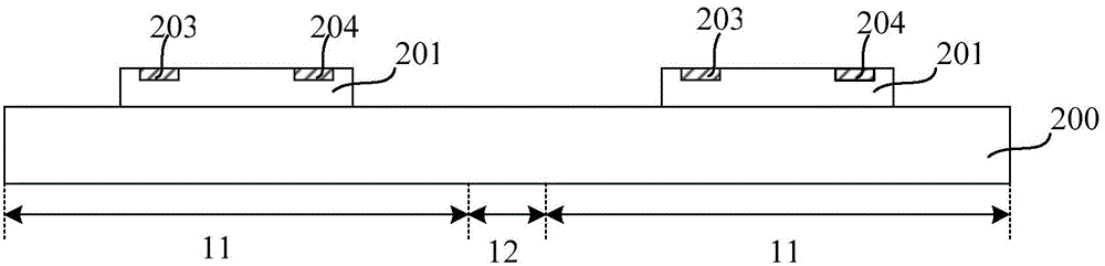
[0028] After research, in the existing technology, when forming a radio frequency module, the radio frequency identification antenna and the radio frequency integrated chip are manufactured separately. The metal connection wire is formed by the bonding process to electrically connect a single RFID antenna and the RF integrated chip to form a radio frequency module, which reduces the production efficiency, and the RFID antenna and the RF integrated chip need to be pasted on the carrier board and then electrically connected through a metal wire, so that the formed The radio frequency module occupies a relatively large area and volume.

[0029] After further research, the radio frequency identification antenna needs to meet a certain length when used and designed, so the size of the radio frequency identification antenn...


PUM


Abstract

A radio frequency module forming method comprises the following steps: a carrier plate including a plurality of chip areas and cutting channel areas is provided; radio frequency integrated chips are provided, and the radio frequency integrated chips are pasted on the chip areas of the carrier plate, wherein each radio frequency integrated chip includes a first pad and a second pad; a first plastic package layer covering the surfaces of the radio frequency integrated chips and the carrier plate is formed, wherein the first plastic package layer is internally provided with a first metal column electrically connected with the first pad and a second metal column electrically connected with the second pad, and the first plastic package layer exposes the first metal column and the second metal column; a radio frequency identification antenna is formed on the first plastic package layer, wherein the radio frequency identification antenna includes a first end and a second end and extends from the first end to the second end, the first end is electrically connected with the first metal column, and the second end is electrically connected with the second metal column; and the first plastic package layer and the carrier plate are cut along the cutting channel areas to form a plurality of separate radio frequency modules. By adopting the method of the invention, the area occupied by the radio frequency modules can be reduced, and the radio frequency module making efficiency can be improved.

Description

technical field [0001] The invention relates to radio frequency identification technology, in particular to a method for forming a radio frequency module. Background technique [0002] RFID (Radio Frequency Identification: Radio Frequency Identification) is a non-contact automatic identification technology, which automatically identifies the target object and obtains relevant data through radio frequency signals, and the identification work does not require manual intervention. [0003] The basic RFID system consists of two parts: a reader (Reader) and a transponder (Transponder). The transponder is also called a radio frequency module. The transponder (Transponder): consists of a radio frequency identification antenna and a radio frequency integrated chip. [0004] The working principle of the RFID system is: the reader transmits a specific frequency signal to the transponder (Transponder), which is used to drive the internal circuit in the transponder (Transponder) to send...

Claims


Application Information

Patent Timeline
IPC IPC(8): H01L21/84
CPCG06K19/07722H01L21/4853H01L23/66H01Q1/2208H01Q1/2283
Inventor 石磊
Owner NANTONG FUJITSU MICROELECTRONICS
Why Eureka
Try Eureka