Plant culture frame

A technology for cultivation racks and plants, applied in the field of plant cultivation racks, can solve the problems of waste of water resources, poor cooling effect, and poor control of the amount of access, and achieve the effects of saving water resources and good cooling effect.

Inactive Publication Date: 2014-10-01
王琬
View PDF8 Cites 11 Cited by
  • Summary
  • Abstract
  • Description
  • Claims
  • Application Information

AI Technical Summary

Problems solved by technology

[0003] The provision of nutrients is generally realized by passing nutrient solution into the plant incubator, which requires manual and regular supply of nutrient solution, which not only consumes a lot of energy, but also the amount of nutrient intake is not easy to control, which affects the accuracy of the e

Method used


Image

  • Plant culture frame
  • Plant culture frame

Examples


Embodiment 1

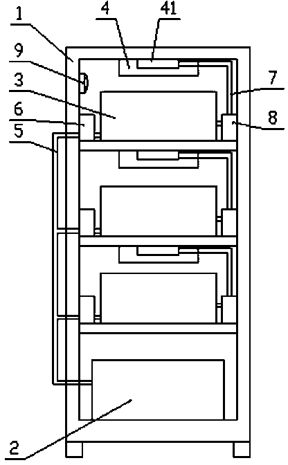
[0020] This embodiment provides a plant cultivation frame, such as figure 1 As shown, the plant cultivation frame includes a frame 1, which is divided into four space layers by partitions from top to bottom, the bottom space layer is provided with a nutrient solution tank 2, and the other three space layers are provided with plant cultivation Box 3, LED lighting lamp 4 is installed on the top of the space layer that is provided with plant cultivation box 3. A heat sink 41 is arranged on the LED lighting lamp 4 , and a cooling water channel is provided in the heat sink 41 .

[0021] Each plant cultivation box 3 communicates with the nutrient solution tank 2 through the liquid inlet pipeline 5, and the first water pump 6 is arranged on the liquid inlet pipeline 5, and each plant cultivation box 3 communicates with the heat sink 41 through the liquid outlet pipeline 7. The inlets of the cooling water channels are connected, and the second water pump 8 is arranged on the outlet p...

Embodiment 2

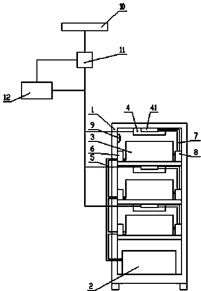
[0028] This embodiment provides a plant cultivation frame, such as figure 2 As shown, the structure of the plant cultivation frame is basically the same as that of Embodiment 1, including a frame 1, which is divided into four space layers by partitions from top to bottom, the bottom space layer is provided with a nutrient solution tank 2, and the other three Each space layer is provided with a plant cultivation box 3, and an LED lighting lamp 4 is installed on the top of the space layer provided with the plant cultivation box 3. A heat sink 41 is arranged on the LED lighting lamp 4 , and a cooling water channel is provided in the heat sink 41 . Each plant cultivation box 3 is connected with the nutrient solution tank 2 through the first water pump 6 , and connected with the cooling water channel in the heat sink 41 through the second water pump 8 .

[0029] The difference is that the plant cultivating frame of this embodiment also includes a photovoltaic solar panel 10 insta...


PUM


Abstract

The invention discloses a plant culture frame, relates to the technical field of bioengineering, and is designed for solving the problems of waste of water source and the like in the conventional plant culture frame. The plant culture frame comprises a framework; the framework is partitioned into a plurality of space layers from top to bottom through clapboards; the bottommost space layer is provided with a nutrient solution tank; plant culture tanks are arranged in other space layers; LED (Light-Emitting Diode) illuminating lamps are arranged on the tops of the space layers in which the plant culture tanks are arranged; the LED illuminating lamps are provided with heat sinks; cooling water channels are formed in the heat sinks; each plant culture tank is connected with the nutrient solution tank through a first water pump, and is connected with the cooling water channel in each heat sink through a second water pump. Nutrient solution in the nutrient solution tank is conveyed into the plant culture tanks through the first water pumps, nutrient substances are absorbed by plants, and residual water is conveyed to the cooling water channel in the heat sinks through the second water pumps for cooling the LED illuminating lamps, thereby achieving a good cooling effect, and greatly saving water sources.

Description

technical field [0001] The invention relates to the technical field of bioengineering, in particular to a plant cultivation frame. Background technique [0002] With the continuous advancement of science and technology, new agricultural development research has become more and more important. Plants are artificially improved, the original genes and molecular structures of plants are changed, and new varieties are developed to achieve the desired indicators. In the process of conducting these experiments, it is necessary to create an artificial climate environment for plants in order to carry out various scientific experiments. This artificial climate environment includes several major elements necessary for plant growth: temperature, humidity, light, nutrients, etc. [0003] The provision of nutrients is generally realized by passing nutrient solution into the plant incubator, which requires manual and regular supply of nutrient solution, which not only consumes a lot of ene...

Claims


Application Information

Patent Timeline
IPC IPC(8): A01G31/06
CPCY02P60/21
Inventor 王琬
Owner 王琬
Why Eureka
Try Eureka