Side door lock drive mechanism

A transmission mechanism and side door technology, which is applied in the field of automobile door lock systems, can solve problems such as poor reliability, large transmission force, and complex structure, and achieve the effects of reduced transmission force, simple structure, and simple and compact product structure

Active Publication Date: 2016-08-24
无锡忻润汽车安全系统有限公司
View PDF6 Cites 0 Cited by
  • Summary
  • Abstract
  • Description
  • Claims
  • Application Information

AI Technical Summary

Problems solved by technology

[0003] The existing functional mechanisms for dragging in the clamping plate are all rotated through the center of the connecting rod, and finally realize this function by driving the ratchet. The structure is complex, the work reliability is poor, and the required transmission force is large. The gear reduction ratio realizes this function

Method used


Image

  • Side door lock drive mechanism
  • Side door lock drive mechanism
  • Side door lock drive mechanism

Examples


Embodiment Construction

[0014] Below in conjunction with specific accompanying drawing and embodiment the utility model is further described.

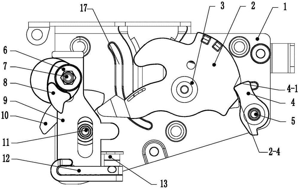
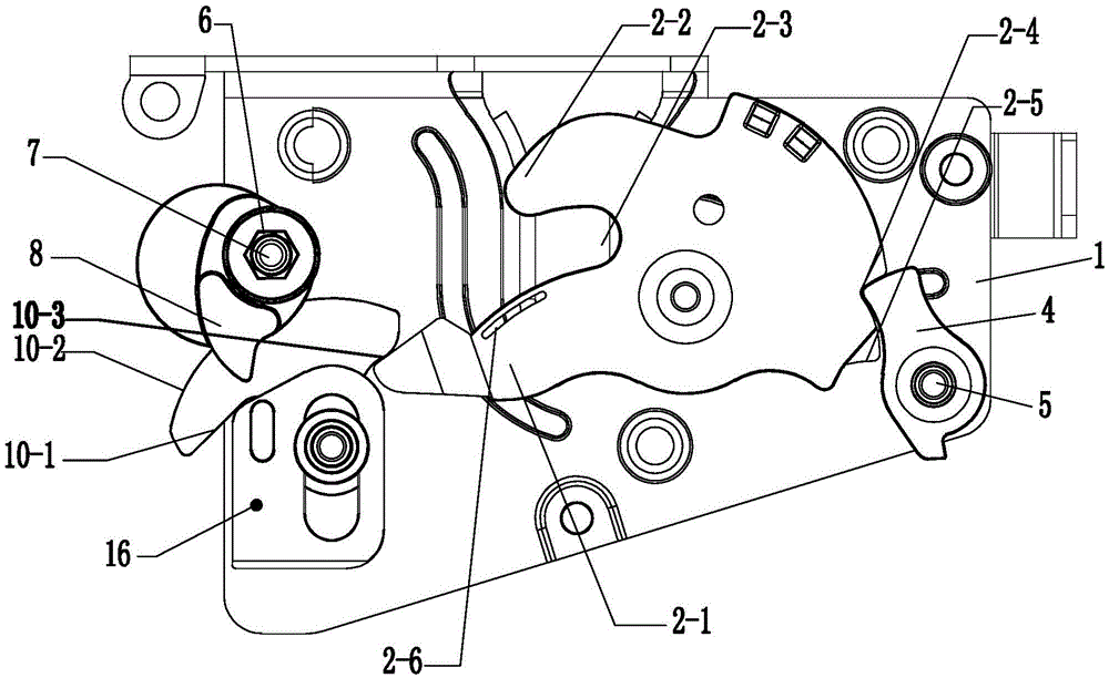
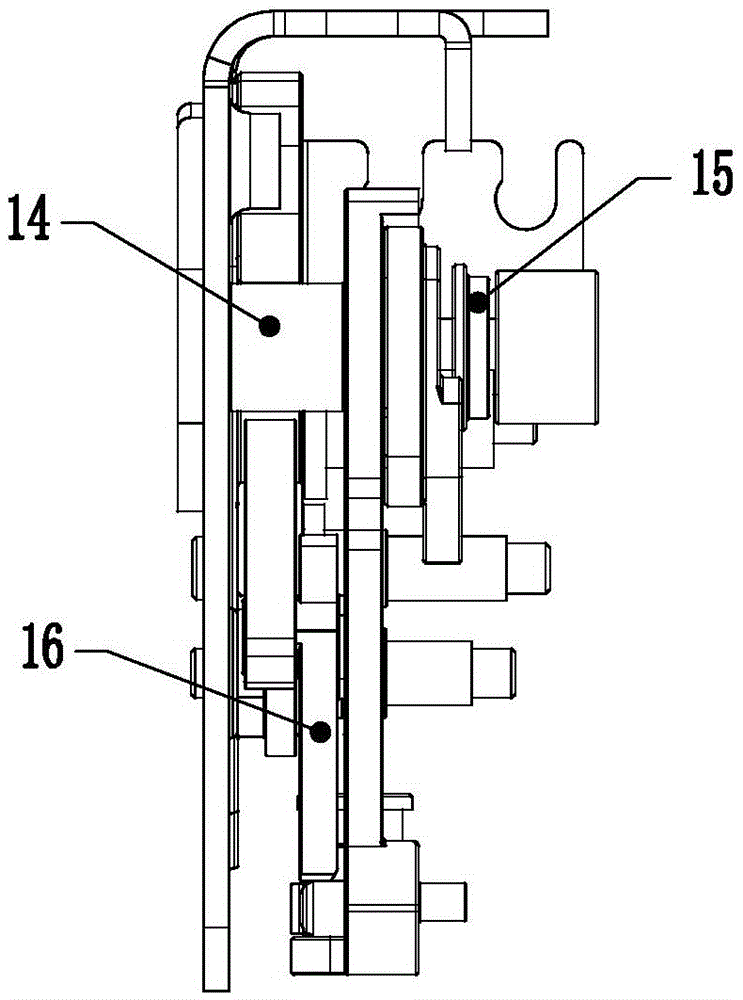
[0015] like Figure 1~3 As shown, it includes bottom plate 1, ratchet 2, force arm 2-1, arc claw 2-2, groove 2-3, semi-locking engagement arc surface 2-4, full lock engagement arc surface 2-5, Damping groove 2-6, ratchet riveting shaft 3, pawl 4, claw end 4-1, pawl riveting shaft 5, coupling 6, transmission shaft 7, transmission cam 8, slider 9, self-priming cam 10, Concave surface 10-1, convex surface 10-2, end force application surface 10-3, slider positioning shaft 11, clutch arm 12, clutch arm riveting shaft 13, drive shaft lower bearing 14, drive shaft upper bearing 15, self-priming cam Push plate 16, sliding support boss 17 etc.

[0016] like Figure 1~3 As shown, a side door lock transmission mechanism of the utility model includes a base plate 1, on which a ratchet riveting shaft 3 and a pawl riveting shaft 5 are fixed, and the ratchet 2 is rotatab...


PUM


Abstract

The invention belongs to the field of automobile door lock systems, and specifically relates to a side door lock transmission mechanism, which includes a bottom plate, on which a ratchet riveting shaft and a pawl riveting shaft are fixed, and the ratchet is rotatably connected to the ratchet riveting shaft. The claw is rotatably connected to the ratchet riveting shaft, and the front claw end of the ratchet leans against the locking and engaging arc surface of the ratchet wheel; a drive shaft is arranged on the end of the bottom plate away from the ratchet riveting shaft to rotate. The cam is connected to the transmission shaft with an interference fit, and a slider positioning shaft is arranged on the bottom plate corresponding to the bottom of the transmission shaft. The structure of the product of the present invention is simple and compact, and the transmission force can be effectively reduced by setting the connecting rod slider cam structure on the bottom plate, the structure is simple, and the transmission efficiency and transmission stability are greatly improved.

Description

technical field [0001] The utility model belongs to the field of automobile door lock systems, in particular to a side door lock transmission mechanism. Background technique [0002] The function of electric dragging into the clamp is a new type of car door lock function produced with the development of control technology. The lock ratchet drives the lock into a fully locked state. [0003] The existing functional mechanisms for dragging in the clamping plate are all rotated through the center of the connecting rod, and finally realize this function by driving the ratchet. The structure is complex, the work reliability is poor, and the required transmission force is large. The gear reduction ratio accomplishes this function. Contents of the invention [0004] The purpose of the utility model is to overcome the deficiencies in the prior art and provide a simple, ingenious and reasonable side door lock transmission mechanism, which can greatly improve the transmission effi...

Claims


Application Information

Patent Timeline
Patent Type & Authority Patents(China)
IPC IPC(8): E05B79/10E05B83/36
Inventor 谢长江彭跃林徐迎庆贾现春邹强黄荣
Owner 无锡忻润汽车安全系统有限公司
Why Eureka
Try Eureka