Debuggable movable hydraulic oil source

A technology of hydraulic oil source and hydraulic oil, which is applied in the direction of fluid pressure actuation device, fluid pressure actuation system components, mechanical equipment, etc., can solve the problems of low precision and non-adjustment.

Active Publication Date: 2014-10-01
BEIJING MECHANICAL EQUIP INST
View PDF6 Cites 4 Cited by
  • Summary
  • Abstract
  • Description
  • Claims
  • Application Information

AI Technical Summary

Problems solved by technology

[0003] The purpose of the present invention is to provide a mobile hydraulic oil source that can be adjusted to solve the problem that the parameters of the oil source pressure, flow rate and temperature in the heat exchange test are not accurate or cannot be adjusted.

Method used


Image

  • Debuggable movable hydraulic oil source

Examples


Embodiment Construction

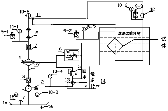
[0010] An adjustable mobile hydraulic oil source, including: hydraulic pump 1, motor 2, check valve 3, oil filter 4, overflow valve 5, speed control valve 6, throttle valve 7, liquid level gauge 15, stop valve 16 , three-way ball valve 11, air filter 17, oil pipe 19 and fuel tank 18, also includes: electric heater A8-1, electric heater B8-2, pressure sensor A9-1, pressure sensor B9-2, pressure sensor C9-3 , temperature sensor A10-1, temperature sensor B10-2, temperature sensor C10-3, temperature sensor D10-4, temperature sensor E10-5, temperature sensor F10-6, flow sensor 12, heat exchanger 13 and proportional water valve 14 . The bottom of the fuel tank is connected to the shut-off valve 16 through a pipe joint, the air filter 17 is installed on the top of the fuel tank through bolts, the fuel tank 18 is connected to the oil suction port of the hydraulic pump 1 through a hard pipe, and the input shaft of the hydraulic pump 1 is connected to the motor 2 through a coupling And...


PUM


Abstract

The invention discloses a debuggable movable hydraulic oil source. The debuggable movable hydraulic oil source comprises a hydraulic pump, a motor, a check valve, an oil filter, an overflow valve, a speed regulation valve, a throttle valve, an electric heater, a pressure sensor, a temperature sensor, a three-way ball valve, a flow sensor, a heat exchanger, a proportion water valve, a liquid level meter, a cut-off valve, an air filter, an oil tank and an oil tube, wherein all the components are connected by the oil tube and tube joints; the three-way ball valve is adjusted, and the pump motor and the electric heater are started to carry out self-circulation heating for oil in an oil tanker; then the three-way ball valve is adjusted, the throttle valve and the speed regulation valve are adjusted to adjust a system flow to a target value, a target temperature value is input in an operation interface, and then various tests are carried out on the tested equipment. The source disclosed by the invention solves the problem of low or nonadjustable accuracies of parameters of an oil source pressure, a flow, a temperature and the like of a heat exchange test.

Description

technical field [0001] The invention relates to a hydraulic oil source, in particular to a movable hydraulic oil source which can be adjusted. Background technique [0002] The working medium of the current aircraft hydraulic system requires that the long-term working temperature should not exceed 100°C (short-term 125°C) under any working conditions, and the hydraulic system will generate heat due to power loss when it is working, and the heat will be transferred to the working medium, making the system The temperature rises, which may cause the system working medium temperature to be too high. Excessive temperature of the hydraulic system is one of the important causes of hydraulic system failure, which seriously affects the safety of the system. Therefore, it is necessary to take necessary heat dissipation and cooling measures. The aircraft hydraulic system generally adopts the fuel-hydraulic oil heat dissipation method, which can effectively meet the heat dissipation r...

Claims


Application Information

Patent Timeline
Patent Type & Authority Applications(China)
IPC IPC(8): F15B21/04F15B21/08
Inventor 董凯张利剑崔广志
Owner BEIJING MECHANICAL EQUIP INST
Why Eureka
Try Eureka