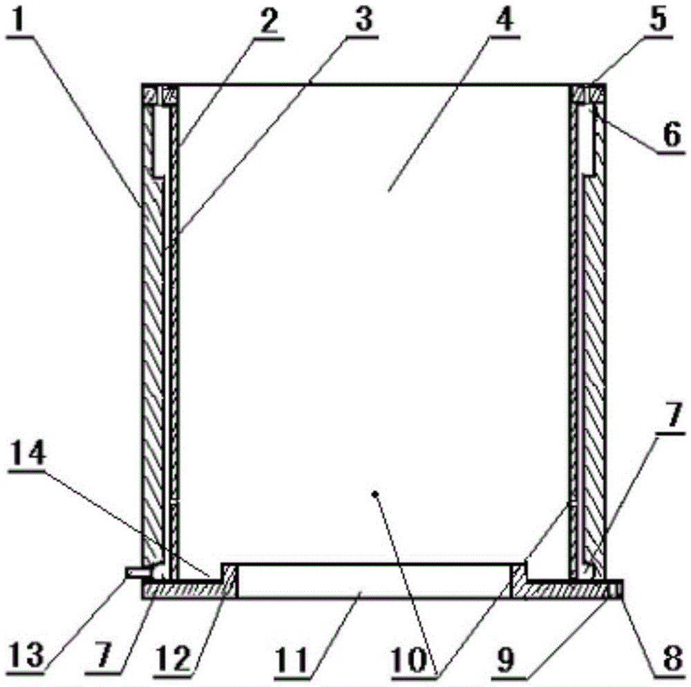
A liquid fuel gasification burner
A liquid fuel and burner technology, applied in the direction of burner, combustion method, combustion type, etc., can solve the problems of liquid leakage, high pressure, bad, etc., and achieve the effect of uniform dispersion of fire, improved thermal efficiency, and good heating effect
- Summary
- Abstract
- Description
- Claims
- Application Information
AI Technical Summary
Problems solved by technology
Method used
Image
Examples
Embodiment 1
[0029] Such as figure 1 As shown, the burner is a tube burner, which includes a casing 1, a heat transfer layer 2, a gasification interlayer 3, a gas hole 5, an air storage tank 6, a liquid distribution tank 7, a liquid fuel hole 10, an air port 11 and Liquid supply connection pipe 13; the shell 1 is connected with the two ends of the heat transfer layer 2 to form a gasification interlayer 3, the interlayer thickness of the gasification interlayer 3 is 0.04cm, and the middle of the tube is a heat supply chamber; the bottom of the burner Bottom plate 12 is arranged at the end, and bottom plate 12 is provided with anti-oil spill ring groove 14, and the middle of anti-oil spill ring groove 14 is air port 11, and the outer circle of bottom plate 12 is provided with 3 fixed ears 8; Said fixed ears 8 and support feet use bolt holes 9 is fixed and installed in the furnace hall; the inner ring of the upper section of the shell 1 is provided with a square annular gas storage tank 6, an...
Embodiment 2
[0031] Such as figure 1 As shown, the burner is a tube burner, which includes a casing 1, a heat transfer layer 2, a gasification interlayer 3, a gas hole 5, an air storage tank 6, a liquid distribution tank 7, a liquid fuel hole 10, an air port 11 and The liquid supply connection pipe 13; the two ends of the shell 1 and the heat transfer layer 2 are connected to form a gasification interlayer 3, the interlayer thickness of the gasification interlayer 3 is 0.07cm, and the middle of the tube is a heat supply chamber; the bottom of the burner Bottom plate 12 is arranged at the end, and bottom plate 12 is provided with anti-oil spill ring groove 14, and the middle of anti-oil spill ring groove 14 is air port 11, and the outer circle of bottom plate 12 is provided with 4 fixed ears 8; Described fixed ear 8 is provided with bolt hole 9; The inner ring of the upper part of the casing 1 is provided with a square annular gas storage tank 6, and the end of the casing 1 is provided with...
Embodiment 3
[0033] Such as figure 1 As shown, the burner is a tube burner, which includes a casing 1, a heat transfer layer 2, a gasification interlayer 3, a gas hole 5, an air storage tank 6, a liquid distribution tank 7, a liquid fuel hole 10, an air port 11 and Liquid supply connection pipe 13; the shell 1 is connected with the two ends of the heat transfer layer 2 to form a gasification interlayer 3, the interlayer thickness of the gasification interlayer 3 is 0.09cm, and the middle of the tube is a heat supply chamber; the bottom of the burner Bottom plate 12 is arranged at the end, and bottom plate 12 is provided with anti-oil spill ring groove 14, and the middle of anti-oil spill ring groove 14 is air port 11, and the outer circle of bottom plate 12 is provided with 4 fixed ears 8; Described fixed ear 8 is provided with bolt hole 9; The inner ring of the upper part of the casing 1 is provided with a square annular gas storage tank 6, and the end of the casing 1 is provided with mor...
PUM
 Abstract
Description
Claims
Application Information
 - R&D
- Intellectual Property
- Life Sciences
- Materials
- Tech Scout
- Unparalleled Data Quality
- Higher Quality Content
- 60% Fewer Hallucinations
Browse by: Latest US Patents, China's latest patents, Technical Efficacy Thesaurus, Application Domain, Technology Topic, Popular Technical Reports.
© 2025 PatSnap. All rights reserved.Legal|Privacy policy|Modern Slavery Act Transparency Statement|Sitemap|About US| Contact US: help@patsnap.com

