A New Furnace Cavity Pressure Control Device

A pressure control and furnace chamber technology, applied in furnace control devices, furnaces, furnace components, etc., can solve the problems of short service life of gates and affect production work, and achieve the effects of improving thermal efficiency, saving costs, and improving work efficiency

Active Publication Date: 2015-10-21
SUZHOU BONENG FURNACE TECH CO LTD
View PDF5 Cites 0 Cited by
  • Summary
  • Abstract
  • Description
  • Claims
  • Application Information

AI Technical Summary

Problems solved by technology

The gate is under high temperature and corrosion for a long time, the service life of the gate is short, and the gate needs to be replaced frequently
However, the replacement of the ram needs to stop production, thus affecting the normal production work

Method used


Image

  • A New Furnace Cavity Pressure Control Device
  • A New Furnace Cavity Pressure Control Device

Examples


Embodiment Construction

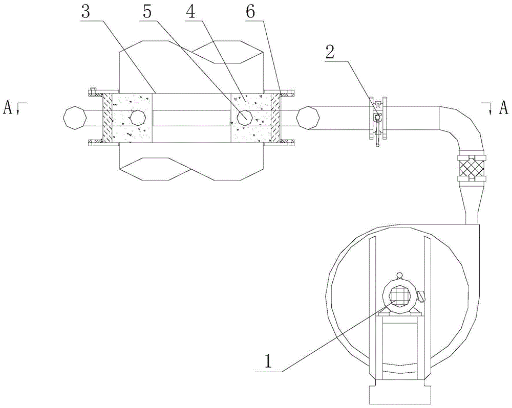
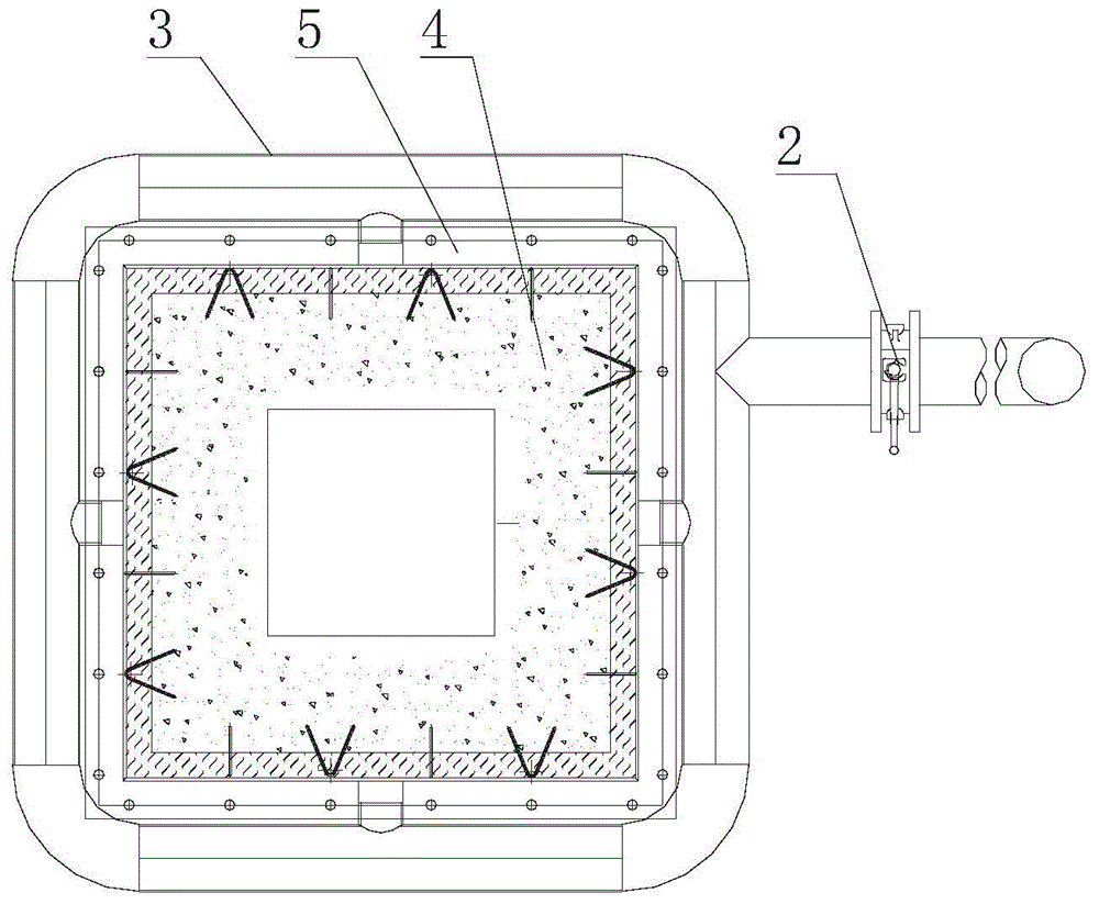
[0017] Such as Figure 1 to Figure 2 As shown, as the first preferred embodiment, this embodiment provides a novel furnace chamber pressure control device, which is arranged on the auxiliary smoke exhaust pipe of the industrial furnace, and is used to control the furnace chamber pressure of the industrial furnace, including a pressure sensor (in the figure not shown), a rectangular smoke lock body 3 and a fan 1, the smoke lock body 3 is provided with a smoke lock axial cavity, and the inside of the smoke lock axial cavity is provided with a refractory casting layer 4, and the refractory casting layer 4 is provided with There is an axial port, and a sealed steel pipe 5 is arranged around the axial port in the refractory castable layer 4. A number of air holes are arranged on the inner wall of the airtight steel pipe 5, and the air holes are arranged on the side close to the axial port and distributed on the axial On the same vertical plane, the pressure sensor is arranged in th...


PUM


Abstract

The invention relates to a novel furnace chamber pressure control device which is arranged on an auxiliary smoke discharging tube of an industrial furnace and is used for controlling the furnace chamber pressure of the industrial furnace. The novel furnace chamber pressure control device comprises a pressure sensor, a smoke brake body and a draught fan. The smoke brake body is provided with a smoke brake axial cavity, and a fire-resistant pouring layer is arranged on the inner wall of the smoke brake axial cavity. An axial opening is formed in the fire-resistant pouring layer, and a closed steel tube is arranged around the axial opening in the fire-resistant pouring layer. A plurality of air holes are formed in the inner wall of the closed steel tube, and the air holes are distributed in the at least same plane perpendicular to the smoke brake axial cavity. The pressure sensor is arranged in a furnace chamber of the industrial furnace, the axial opening is communicated with the auxiliary smoke discharging tube, and the draught fan is communicated with the closed steel tube. According to the novel furnace chamber pressure control device, a plane brake is formed by the blast capacity of the draught fan, so that the quality and capacity exchange on the two side areas of the plane brake is reduced, high-precision control over the furnace chamber pressure is achieved, and the heat efficiency of equipment is improved. Compared with the prior art, a brake plate does not need to be replaced, production work does not need to be stopped, cost is saved, and the working efficiency is improved.

Description

technical field [0001] The invention belongs to the field of industrial furnace machinery, in particular to a novel furnace chamber pressure control device. Background technique [0002] Various flame furnaces in the aluminum industry use rams to adjust the discharge of flue gas in the furnace to control the pressure of the furnace chamber. Traditional rams are made of heat-resistant castings or refractory castables. The gate is under high temperature and corrosion for a long time, the service life of the gate is short, and the gate needs to be replaced frequently. However, replacing the ram needs to stop production, thus affecting normal production work. [0003] Therefore, there is an urgent need for a furnace chamber pressure control device that does not affect normal production work. Contents of the invention [0004] The purpose of the present invention is to overcome the defects in the prior art and provide a novel furnace chamber pressure control device. [0005]...

Claims


Application Information

Patent Timeline
Patent Type & Authority Patents(China)
IPC IPC(8): F27D17/00F27D7/00F27D19/00
Inventor 齐青左建中邵杰
Owner SUZHOU BONENG FURNACE TECH CO LTD
Why Eureka
Try Eureka