Large-view-field photoelectric auto-collimator for secondary imaging

A photoelectric autocollimator and secondary imaging technology, applied in optics, instruments, optical components, etc., can solve the problems of large measurement range and high measurement accuracy

Inactive Publication Date: 2014-10-01
HUAZHONG AGRICULTURAL UNIVERSITY
View PDF6 Cites 9 Cited by
  • Summary
  • Abstract
  • Description
  • Claims
  • Application Information

AI Technical Summary

Problems solved by technology

Due to the limitation of the size of the photosensitive surface of the detector and the size of the pixel, the current photoelectric aut

Method used


Image

  • Large-view-field photoelectric auto-collimator for secondary imaging
  • Large-view-field photoelectric auto-collimator for secondary imaging
  • Large-view-field photoelectric auto-collimator for secondary imaging

Examples


Example Embodiment

[0019] The present invention will be further described in detail below in conjunction with the drawings and specific embodiments:

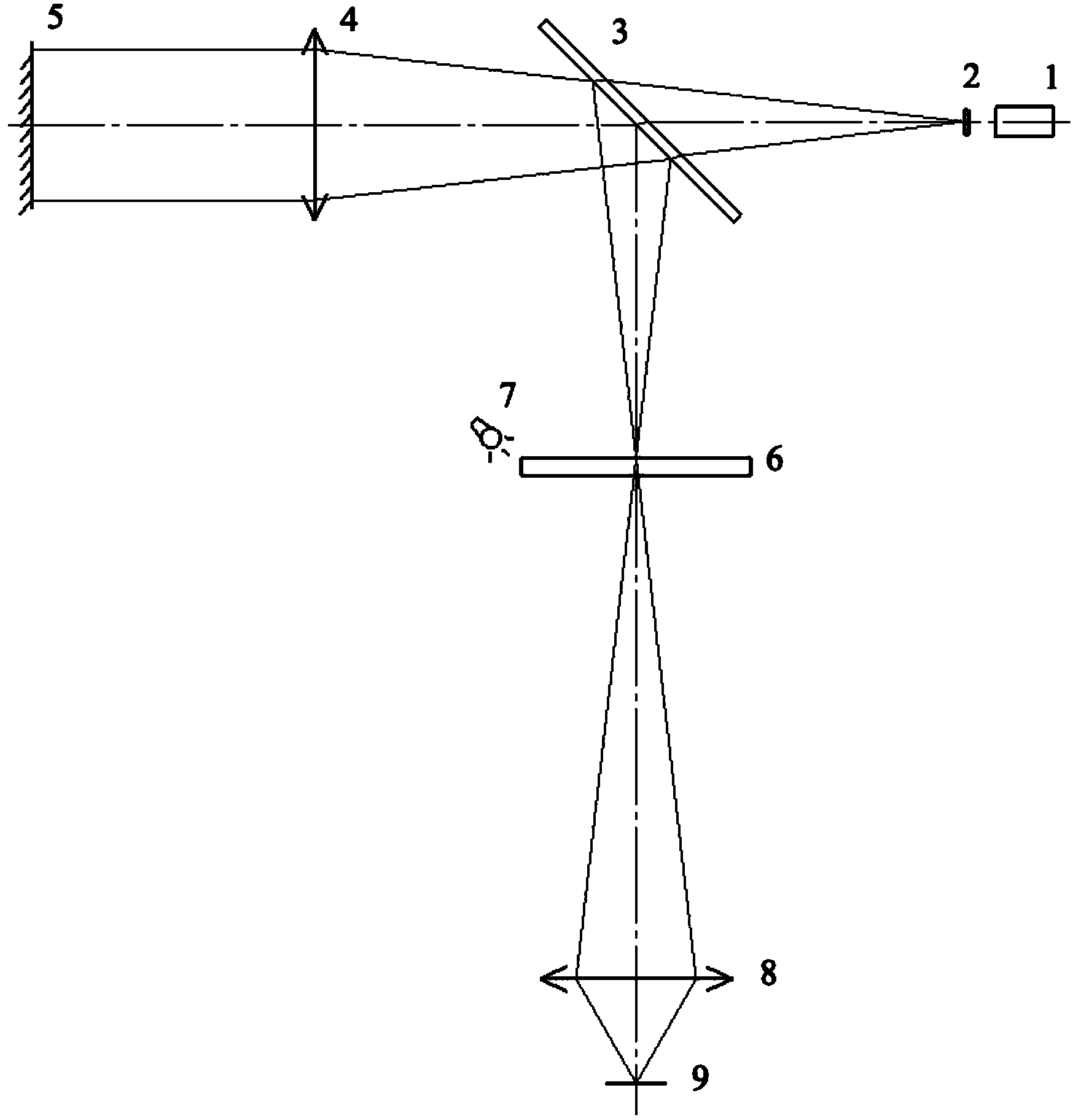
[0020] Such as figure 1 As shown, the structure of the entire system mainly includes semiconductor laser 1, illumination reticle 2, beam splitter 3, collimating objective lens group 4, measuring reticle 6, white light LED7, CCD imaging objective lens 8, CCD9 (high-definition CCD 4 million Pixels), aperture group 10. The laser light emitted by the semiconductor laser 1 emits a thin beam of laser light through the dark bottom bright line cross reticle of the illuminated reticle 2, and then passes through the beam splitter 3 and is incident on the external mirror 5 through the collimating objective lens group 4. The external mirror 5 After the reflected light beam passes through the collimating objective lens group 4 and the beam splitter 3, it is reflected and imaged onto the measuring reticle 6. When the external reflector 5 is tilted, the light beam...


PUM


Abstract

The invention discloses a large-view-field photoelectric auto-collimator for secondary imaging. The large-view-field photoelectric auto-collimator comprises a semiconductor laser unit, an illumination reticle, a spectroscope, a collimator objective lens set, a measurement reticle, a CCD imaging objective lens and a CCD. The number of pixels of the CCD is 4 million so that high-definition image measurement can be provided, and the accuracy can meet requirements. The view field of collimator objective lenses is not smaller than 8.5 degrees, and the caliber of the collimator objective lenses is not smaller than 90 mm. After passing through the collimator objective lenses and the spectroscope, light beams reflected back by a reflecting mirror are reflected and form images on ground glass. The CCD is utilized for measuring secondary imaging of light spots on the ground glass. For achieving the system calibration convenience, a ground glass reticle is engraved with two pairs of lines with a fixed interval. For measuring and observing the engraved lines on the ground glass, white-light LED light sources are adopted around for illumination. The ground glass is adopted as the reticles, and therefore the phenomenon that the inclined light beams in the auto-collimator can not enter the CCD can be avoided, the influence that a system interferes with diffraction fringes is eliminated, and the system error is small.

Description

technical field [0001] The invention relates to the field of precision testing and measuring instruments, in particular to a photoelectric autocollimator with a large field of view for secondary imaging. Background technique [0002] Autocollimator is one of the most widely used instruments for angle measurement. The traditional autocollimator has the shortcomings of manual reading and tracking zero error. The photoelectric autocollimator has the advantages of high precision and automatic reading, and has become the mainstream of autocollimator development. The basic principle of the photoelectric autocollimator is to convert the angle change of the reflector into the linear quantity change of the image on the detector for measurement. The development trend of the photoelectric autocollimator is to meet the requirements of large range, high resolution and dynamic measurement. At present, most photoelectric autocollimators use position-sensitive detectors PSD, four-quadrant...

Claims


Application Information

Patent Timeline
IPC IPC(8): G01B11/26G02B27/34
Inventor 谭佐军谢静康竞然
Owner HUAZHONG AGRICULTURAL UNIVERSITY
Why Eureka
Try Eureka