Screw testing machine

A detection machine and screw technology, which is applied in the direction of optical testing for flaws/defects, etc., can solve problems such as the inability to detect screw internal threads, achieve the effect of reducing detection errors and improving detection accuracy

Inactive Publication Date: 2014-10-01
DONGGUAN POLYTECHNIC
View PDF9 Cites 4 Cited by
  • Summary
  • Abstract
  • Description
  • Claims
  • Application Information

AI Technical Summary

Problems solved by technology

However, in the previous screw detection machines, the detection of the internal thread existing in the screw head could not be realized.

Method used


Image

  • Screw testing machine
  • Screw testing machine
  • Screw testing machine

Examples


no. 1 approach

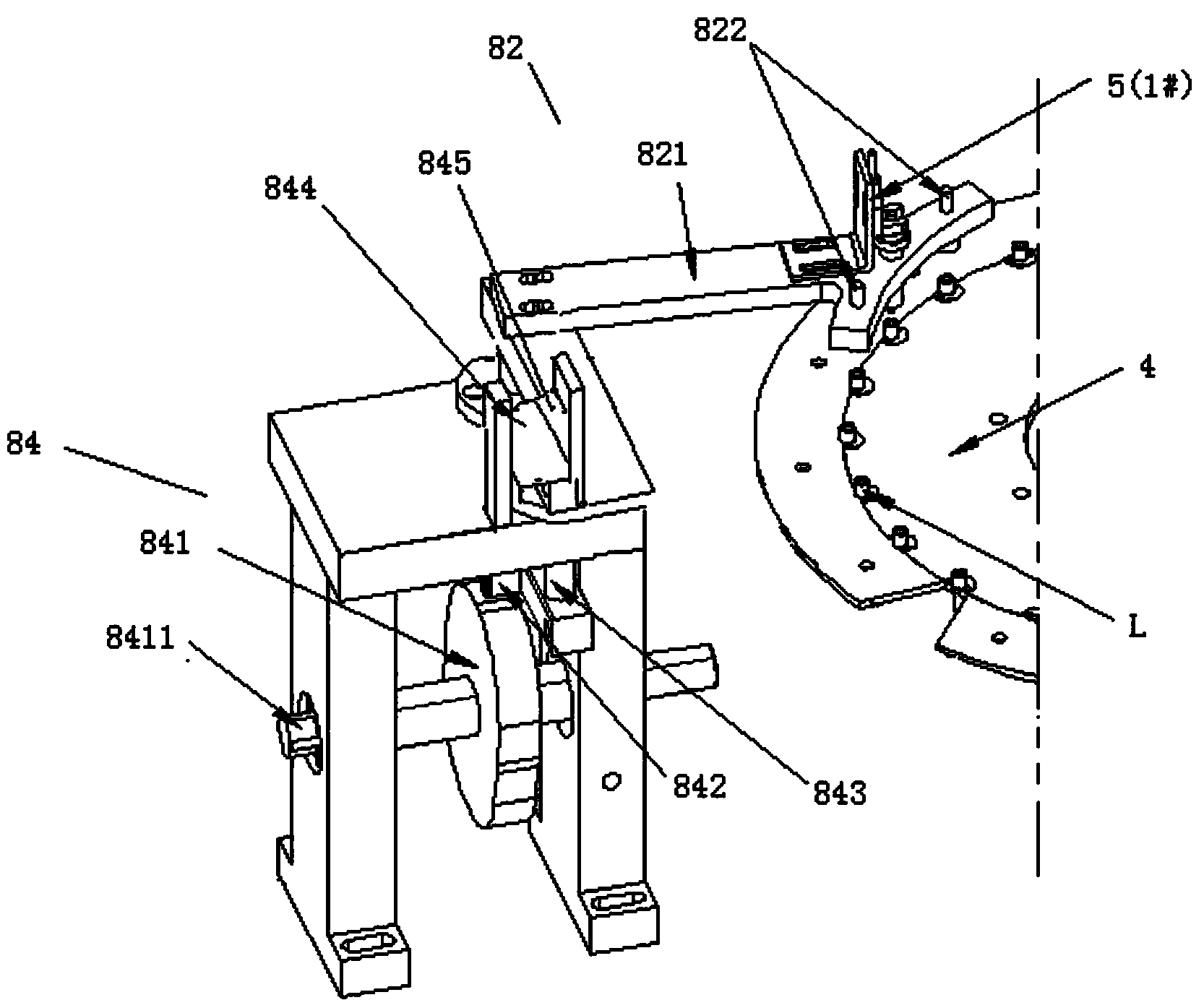
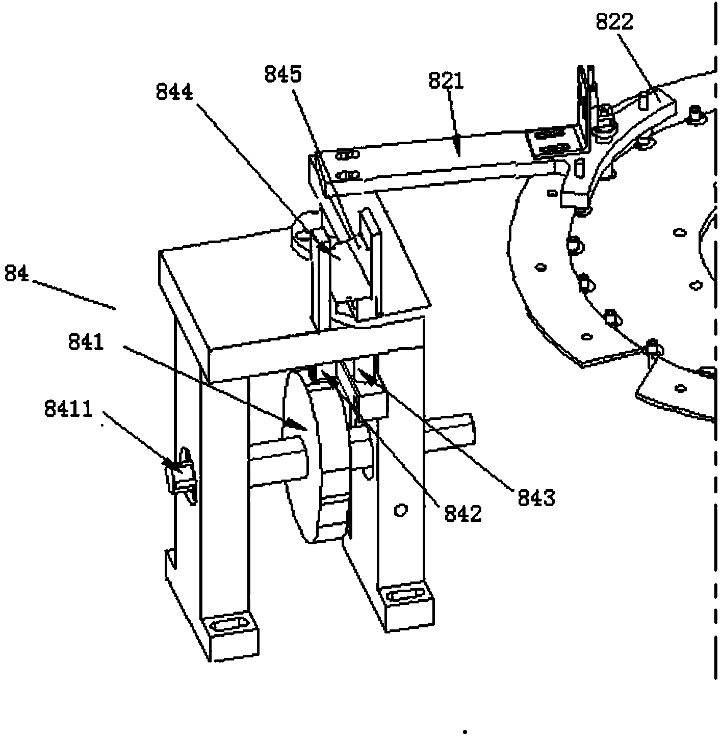
[0035] The solution of the first embodiment mainly solves the problem of detection accuracy caused by the deflection of the screw on the turntable. For this reason, the screw detection machine of this embodiment is provided with a screw position correction mechanism. The screw position correction mechanism and the cam divider of the turntable 4 ( Figure 8 Middle 43) linkage, after the cam divider drives the turntable to rotate one position, it will automatically press down the screw to flatten the screw head on the turntable 4, so as to correct the state of the screw and avoid the detection caused by the abnormal position of the screw error. Hereinafter, this embodiment will be specifically described.

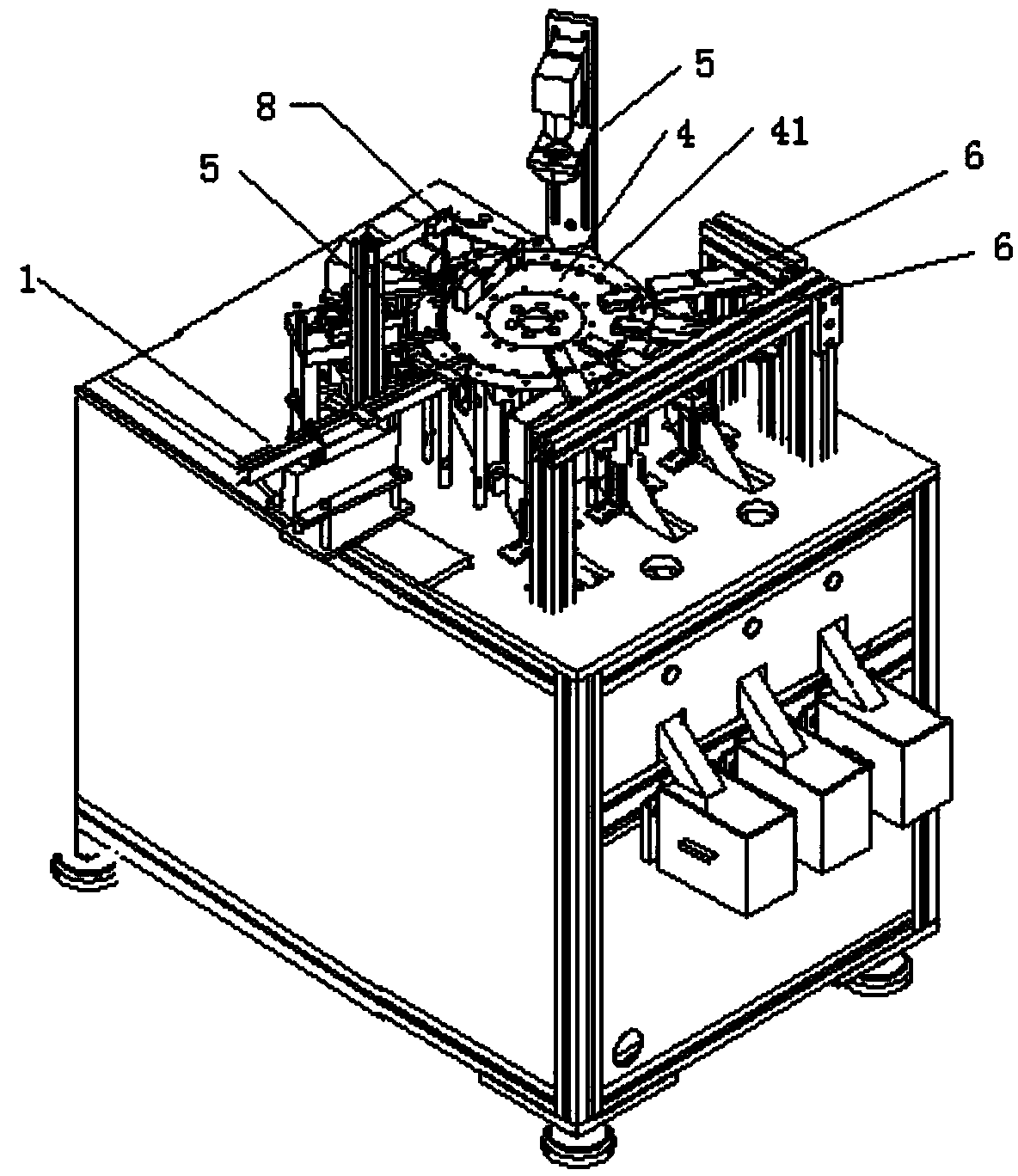
[0036] figure 1 A schematic diagram of a screw inspection machine of the present invention is shown. The screw inspection machine includes a screw loading mechanism 1 , a turntable 4 , a screw defect detector 5 , a plurality of screw recovery mechanisms 6 and a screw posi...

no. 2 approach

[0047] The solution of the second embodiment further improves the solution of the first embodiment for the problem of detection accuracy caused by the deflection of the screw on the turntable 4 . The screw position correction mechanism of the screw detection machine in this embodiment pushes the screw L horizontally after the cam divider drives the turntable to rotate one position, and at the same time automatically presses down the screw to flatten the screw head on the turntable 4 , to correct the state of the screw and avoid the detection error caused by the abnormal position of the screw. Hereinafter, this embodiment will be specifically described.

[0048] The screw inspection machine also includes a screw loading mechanism 1 , a turntable 4 , a screw defect detector 5 , a plurality of screw recovery mechanisms 6 and a screw position correction mechanism 8 . Although figure 1 The number of screw defect detectors 5 marked in is one, but in fact, corresponding to the par...

no. 3 approach

[0059] In this embodiment, the screw placement holes on the turntable are improved, so that the turntable does not need to be replaced when detecting screws of different types or specifications, reducing the use cost of the equipment.

[0060] Figure 6 A part of the back surface of the turntable on which the screw carrier is mounted in the screw inspection machine according to the third embodiment of the present invention is shown. Figure 7 A partial front view of a turntable on which a screw carrier is mounted is shown in a screw inspection machine according to a third embodiment of the present invention.

[0061] Such as Figure 6 and Figure 7 As shown, a screw carrier 42 can be provided in each screw placement hole 41 of the turntable 4 . The three side walls of the screw carrier 42 except one side of the outer edge of the turntable 4 are respectively provided with distance-adjusting screws 422, and the front ends of the distance-adjusting screws 422 are provided with...


PUM


Abstract

The invention relates to a screw testing machine which comprises a screw loading mechanism, a rotary table, a plurality of screw defect detectors, a plurality of screw recovery mechanisms and a screw position correction mechanism, wherein the screw loading mechanism is used for loading screws onto the rotary table; the screws to be tested are respectively arranged in screw placement holes in the rotary table by the screw loading mechanism; the rotary table is used for sending the screws into the corresponding testing positions by rotation; the plurality of screw defect detectors are used for carrying out defect detection on the screws which are rotated to the corresponding positions by the rotary table; the plurality of screw recovery mechanisms comprise at least one defective screw recovering mechanism and at least one accepted screw recovering mechanism; the screw position correction mechanism comprises a screw pressing mechanism and a lifting mechanism, wherein the lifting mechanism is linked with a cam divider of the rotary table; the screw pressing mechanism is connected with the lifting mechanism; when the rotary table rotates and the screws are sent into the correction potions of the screw position correction mechanism, the screw pressing mechanism is driven to press the screws positioned at the corresponding correction potions by the lifting mechanism.

Description

technical field [0001] The invention relates to the field of screw defect detection, in particular to a screw detection machine for detecting defects of precision screws. Background technique [0002] Precision screws are referred to as small screws, also known as tiny screws. They are tiny fasteners that connect product materials. They are small in shape, but they can play a key role in connecting and fastening. They are widely used in electronics, electricity, electrical appliances, furniture, mechanical equipment, etc. . The detection content of precision screws generally includes: head height, diameter and head cracks, deformation, head groove shape, depth and foreign matter, thread part length, outer diameter, inner diameter and pitch, sharp point and broken tail at the end of the thread . [0003] The traditional precision screw inspection method is generally manual sampling inspection, that is, the operator selects a certain number of samples from a batch of product...

Claims


Application Information

Patent Timeline
Patent Type & Authority Applications(China)
IPC IPC(8): G01N21/95
Inventor 朱飞虎
Owner DONGGUAN POLYTECHNIC
Why Eureka
Try Eureka