Supercharge Your Innovation With Domain-Expert AI Agents!

Photoelectric comprehensive cable compact in structure and manufacturing method thereof

An optoelectronic integrated cable with a compact structure, which is used in the manufacture of cables/conductors, insulated cables, communication cables, etc. It can solve the problems of impact, poor pressure performance, high cost, and large structure of optical cables. /Strong impact/bending performance, low cost and high production speed

Inactive Publication Date: 2014-10-01
国网山东省电力公司高密市供电公司 +2
View PDF16 Cites 11 Cited by
  • Summary
  • Abstract
  • Description
  • Claims
  • Application Information

AI Technical Summary

Problems solved by technology

Although the optical cable in this patent achieves the purpose of simple structure, the optical fiber is scattered in the bone leaf, so the structural size of the optical cable is relatively large and the cost is high; in addition, there is only a skeleton body outside the optical fiber, so the optical cable is affected by Impact and compression performance are poor

Method used


Image

  • Photoelectric comprehensive cable compact in structure and manufacturing method thereof
  • Photoelectric comprehensive cable compact in structure and manufacturing method thereof
  • Photoelectric comprehensive cable compact in structure and manufacturing method thereof

Examples


Embodiment 1

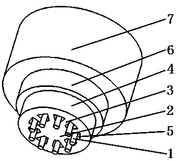
[0043] please see figure 1 and figure 2 , a compact photoelectric integrated cable, which includes nine optical fibers 1, strengthening elements 6, and outer sheath 7, is characterized in that it also includes a central support body 2, a peripheral support body 4, and connects the central support body to the peripheral The nine connecting strips 3 connected by the supporting body, the connecting strip, the outer space of the central supporting body, and the inner space of the peripheral supporting body form nine fiber-containing cavities 5, the optical fibers are located in the fiber-containing cavity and each fiber-containing cavity is radially The width can only accommodate 1 optical fiber, the outer sheath is located outside the outer support body, and the strengthening element is located between the outer support body and the outer sheath.

Embodiment 2

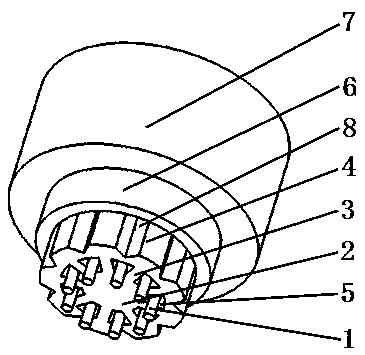
[0045] please see image 3 and Figure 4 , a compact photoelectric integrated cable, which includes nine optical fibers 1, strengthening elements 6, and outer sheath 7, is characterized in that it also includes a central support body 2, a peripheral support body 4, and connects the central support body to the peripheral The nine connecting strips 3 connected by the supporting body, the connecting strip, the outer space of the central supporting body, and the inner space of the peripheral supporting body form nine fiber-containing cavities 5, the optical fibers are located in the fiber-containing cavity and each fiber-containing cavity is radially The width can only accommodate 1 optical fiber, the outer sheath is located outside the peripheral support body, the strengthening element is located in the outer sheath, and there are 2 strengthening elements, which are symmetrically distributed in the outer sheath.

Embodiment 3

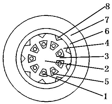
[0047] please see Figure 5 and Figure 6 , a compact photoelectric integrated cable, which includes nine optical fibers 1, strengthening elements 6, and outer sheath 7, is characterized in that it also includes a central support body 2, a peripheral support body 4, and connects the central support body to the peripheral The nine connecting strips 3 connected by the supporting body, the connecting strip, the outer space of the central supporting body, and the inner space of the peripheral supporting body form nine fiber-containing cavities 5, the optical fibers are located in the fiber-containing cavity and each fiber-containing cavity is radially The width can only accommodate 1 optical fiber, the outer sheath is located outside the peripheral support body, the strengthening element is located in the outer sheath, and there are 4 strengthening elements, which are symmetrically distributed in the outer sheath.

[0048] Of course, the reinforcing elements in the implementation...


PUM


Abstract

The invention belongs to the technical field of cables, and particularly relates to a photoelectric comprehensive cable compact in structure. The photoelectric comprehensive cable comprises a plurality of optical fibers, a reinforcement element and an outer protection sleeve, and is characterized by further comprising a central supporting body, a periphery supporting body and a plurality of connecting strips enabling the central supporting body and the periphery supporting body to be connected, a plurality of fiber containing cavities are formed by the connecting strips, the outer space of the central supporting body and the inner space of the periphery supporting body, the optical fibers are located in the fiber containing cavities, the outer protection sleeve is located outside the periphery supporting body, and the reinforcement element is arranged in the outer protection sleeve or between the periphery supporting body and the outer protection sleeve. The invention further discloses a manufacturing method of the photoelectric comprehensive cable. The comprehensive cable has the main advantages of being more compact in structure, smaller in appearance size, lower in size and stronger in pressure / impact / bending resisting performance. The manufacturing method is simple and easy to grasp, production speed is high, consumed electricity is less, and technological cost is low.

Description

technical field [0001] The invention belongs to the technical field of cables, in particular to a photoelectric integrated cable with a compact structure and a manufacturing method thereof. Background technique [0002] In the contemporary society with the rapid development of the communication industry, there is a constant trend for people to miniaturize the optical and cable structures and lower the cost. However, in the context of miniaturization, the performance of optical and cables still needs Only by meeting the requirements of national standards / industry standards can the normal use of users be guaranteed; for this reason, it has brought huge challenges to manufacturers. [0003] Domestic research on light and cable with miniaturization and simplified structure mainly includes the following patents: [0004] The Chinese patent with publication number CN101393310A and application date of 2008.11.05 discloses an optical fiber ribbon cable, which is at least composed ...

Claims


Application Information

Patent Timeline
IPC IPC(8): G02B6/44H01B11/22H01B7/18H01B13/00
CPCG02B6/4429G02B6/443G02B6/4432G02B6/4434H01B7/295H01B11/22
Inventor 尹红
Owner 国网山东省电力公司高密市供电公司
Features
  • R&D
  • Intellectual Property
  • Life Sciences
  • Materials
  • Tech Scout
  • Unparalleled Data Quality
  • Higher Quality Content
  • 60% Fewer Hallucinations
Learn More