
Zoom lens and digital camera

A zoom lens and zoom group technology, applied in the field of zoom lenses and digital cameras, can solve the problems that it is difficult to ensure that the target scene, the near field and the far field are clear at the same time, the zoom lens cannot obtain a sufficient depth of field, and the dispersion coefficient imaging conditions are not well matched. , to achieve the effect of reducing the total appearance length, simple structure and reducing aberration

Active Publication Date: 2014-10-01
ZHEJIANG DAHUA TECH CO LTD
View PDF7 Cites 2 Cited by
  • Summary
  • Abstract
  • Description
  • Claims
  • Application Information

AI Technical Summary

Problems solved by technology

[0003] The existing common zoom lenses generally focus on the target scene clearly, but the close view in front of the target scene or the distant view behind the target scene is blurred, especially in the telephoto part; the main reason for this phenomenon is: the structural shape of the existing zoom lens , the dispersion coefficient and other parameters do not match well with the imaging conditions, so that the zoom lens can only ensure that the target scene and the near view are clear and clear at the same time, or the target scene and the distant view are clear and clear at the same time, that is, the existing zoom lens cannot obtain a large enough depth of field, so it is difficult It is difficult to ensure that the target scene, near view and distant view are clear at the same time

Method used


Image

  • Zoom lens and digital camera
  • Zoom lens and digital camera
  • Zoom lens and digital camera

Examples


Embodiment Construction

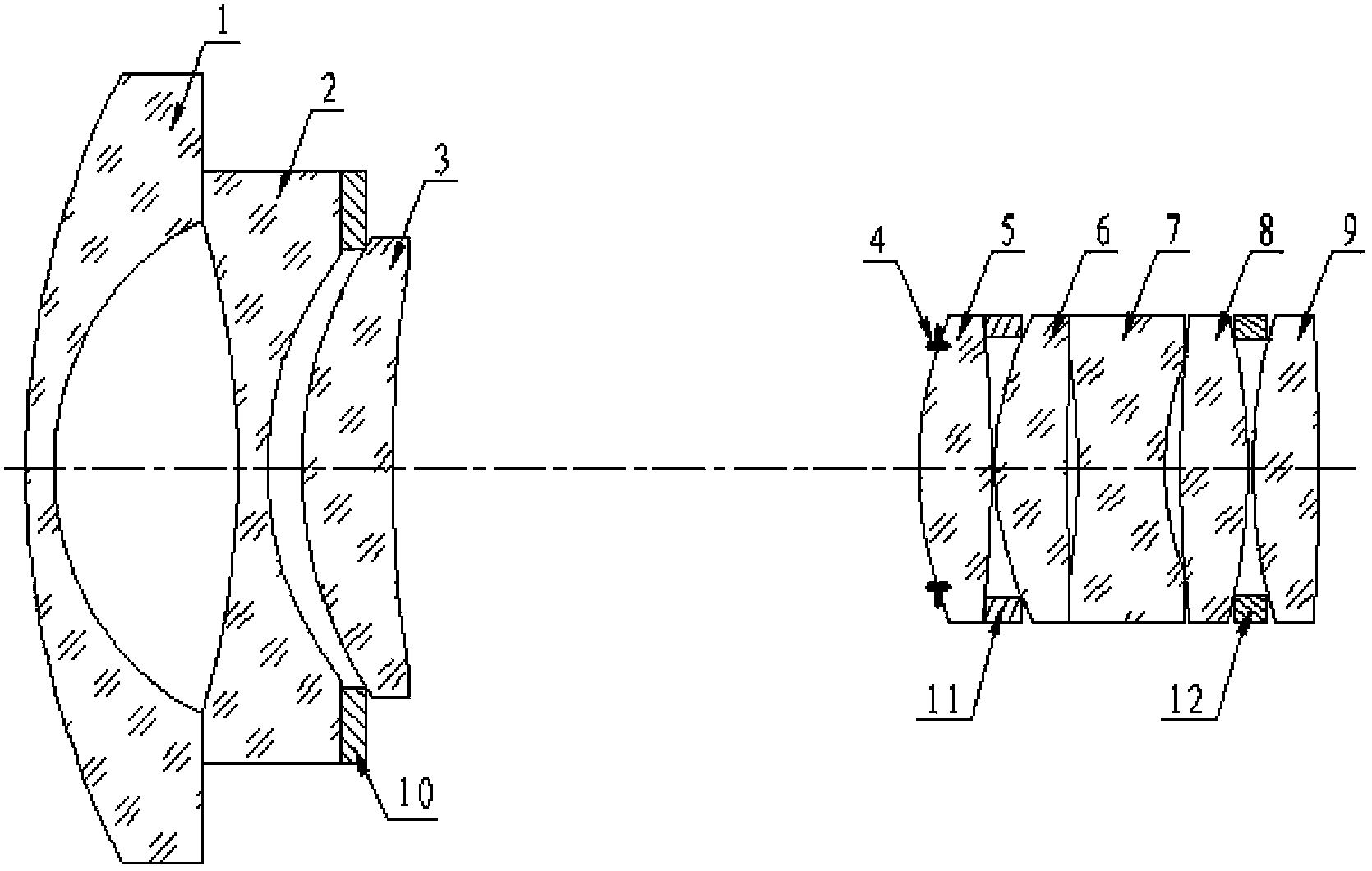
[0030] In order to improve the depth of field of the zoom lens, the present invention provides a zoom lens, which adopts eight lenses of specific structural shapes, arranged in a certain order, and through the distribution of the focal power of each optical lens, the structural shape of the zoom lens , The dispersion coefficient and other parameters match the imaging conditions, and can effectively reduce aberration, chromatic aberration and distortion, so that clear images of the target scene, close-range and distant views can be obtained, and the purpose of improving the depth of field of the zoom lens can be achieved.

[0031] In order to enable those skilled in the art to better understand the technical solutions of the present invention, the embodiments of the present invention will be described in detail below in conjunction with the accompanying drawings.

[0032] Such as figure 1 As shown in , it is a schematic structural diagram of a zoom lens provided by an embodimen...


PUM


Abstract

The invention relates to the technical field of imaging, in particular to a zoom lens and a digital camera. The zoom lens is used for improving the depth of a field of the zoom lens, and therefore a target scene, a target close shot, a target long shot and a sharply focused image can be obtained. The zoom lens comprises a zoom set and a focusing set which are sequentially arranged from the object side to the image side, wherein the zoom set comprises a first convex and concave lens, a first biconcave lens and a first convex lens which are sequentially arranged from the object side to the image side; the convex face of the first convex and concave lens faces the object side, and the focal power of the first convex and concave lens is negative; the focal power of the first biconcave lens is negative; the convex face of the first convex lens faces the object side, and the focal power of the first convex lens is positive; the focusing set comprises a first biconvex lens, a second convex lens, a second biconcave lens, a second biconvex lens and a third biconvex lens, all of which are sequentially arranged from the object side to the image side; the focal power of the first biconvex lens is positive; the convex face of the second convex lens faces the object side, and the focal power of the second convex lens is negative; the focal power of the second biconcave lens is positive; the focal power of the second biconvex lens is positive; the focal power of the third biconvex lens is positive. The invention further discloses the digital camera comprising the zoom lens with the characteristics.

Description

technical field [0001] The invention relates to the field of imaging technology, in particular to a zoom lens and a digital camera. Background technique [0002] A zoom lens refers to a camera lens that can change the focal length within a certain range to obtain images of different sizes and different scene ranges, because it can change the shooting range by changing the focal length without changing the shooting distance, and can reduce the need to carry camera equipment. The number has been widely used. [0003] The existing common zoom lenses generally focus on the target scene clearly, but the close view in front of the target scene or the distant view behind the target scene is blurred, especially in the telephoto part; the main reason for this phenomenon is: the structural shape of the existing zoom lens , the dispersion coefficient and other parameters do not match the imaging conditions well, so that the zoom lens can only ensure that the target scene and the near ...

Claims


Application Information

Patent Timeline
Patent Type & Authority Applications(China)
IPC IPC(8): G02B15/177
Inventor 丁洪兴王丰石礼福张兴明傅利泉朱江明吴军吴坚
Owner ZHEJIANG DAHUA TECH CO LTD
Learn More