Electric automobile charging gun structure

A technology for electric vehicles and charging guns, applied in electric vehicles, battery circuit devices, current collectors, etc., to prevent electromagnetic radiation and leakage, overcome the sharp drop in coupling coefficient, and achieve the effect of high coupling coefficient

Active Publication Date: 2014-10-01
SHANDONG UNIV
View PDF6 Cites 7 Cited by
  • Summary
  • Abstract
  • Description
  • Claims
  • Application Information

AI Technical Summary

Problems solved by technology

[0004] In order to solve the above problems, the present invention proposes a charging gun structure for electric vehicles. This structure does not use metal plug-ins for power supply, so problems such as leakage and poor contact do not occur, and there is no emission / There is a matching problem in the relative position of the receiving coil

Method used


Image

  • Electric automobile charging gun structure
  • Electric automobile charging gun structure
  • Electric automobile charging gun structure

Examples


Embodiment 1

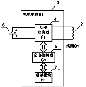
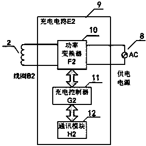
[0090] A charging device for an electric vehicle charging gun of the present invention includes the electrically isolated charging gun shown in Fig. 1 (a), (b) and Fig. 2 (a), (b) and such as Figure 5 with Image 6 Stationary and removable end charging systems shown. The fixed end Figure 1 (a), (b) and Figure 5 When installed inside the electric vehicle, the movable end Fig. 2(a), (b) and Image 6 Connect to the power supply 6 by wires. The specific implementation steps of electric vehicle charging are as follows:

[0091] Step 1. Insert the movable end of the charging gun into the fixed end, and the second magnetic conductor A2 becomes the "barrel cover" of the "barrel-shaped" first magnetic conductor A1, and the two induction coils B1 and B2 promptly becomes the two winding coils of a coupled high-frequency transformer, and the magnetic conductor 1 becomes the iron core of the high-frequency transformer;

[0092] Step 2: The fixed-end charging controller G1(6) detects t...

Embodiment 2

[0096] The charging device of another electric vehicle charging gun of the present invention includes the electrically isolated charging gun shown in Fig. 3 (a), (b) and Fig. 4 (a), (b) and such as Figure 5 with Image 6 Stationary and removable end charging systems shown. The fixed end Figure 3(a), (b) and Figure 5 When installed inside the electric vehicle, the movable end Figure 4(a), (b) and Image 6 Connect to the power supply 6 by wires. The specific implementation steps of electric vehicle charging are the same as those in Embodiment 1.

Embodiment 3

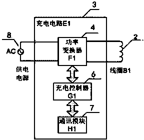
[0098] The charging device of another electric vehicle charging gun of the present invention includes the electrically isolated charging gun shown in Fig. 1 (a), (b) and Fig. 2 (a), (b) and such as Figure 7 with Figure 8 Stationary and removable end charging systems shown. The fixed end Figure 1 (a), (b) and Figure 7 is installed at the power supply end, the movable end Figure 2(a), (b) and Figure 8 placed on the side of the electric vehicle. The specific implementation steps of electric vehicle charging are the same as those in Embodiment 1.


PUM


Abstract

The invention discloses an electric automobile charging gun structure. The electric automobile charging gun structure comprises a fixed end and a movable end. The fixed end and the movable end respectively comprise a magnetizer and an induction coil and can be matched with each other. During charging, the movable end is inserted into the fixed end. Each induction coil is connected with a power converter of a corresponding charging circuit, wherein the power converter is connected with a charging controller, the charging controller is connected with a communication module, the charging controller is used for detecting the input/output voltage and the current of the power converter, receiving a data signal from the communication module, sending the processed data to the communication module and sending a control signal to the power converter. A charging gun is of an electric isolation structure, a metal electrical plugging piece does not exist, and therefore electric leakage, bad contact and other potential safety hazards cannot occur; the electric automobile charging gun structure has a good shielding effect, and electromagnetic radiation is effectively avoided.

Description

technical field [0001] The invention relates to a charging gun structure for an electric vehicle, belonging to the technical field of electric vehicle charging. Background technique [0002] The charging device of an electric vehicle is equivalent to a filling station for vehicle fuel, which can provide energy for the vehicle to run by repeatedly charging the vehicle battery. [0003] At present, the charging devices for electric vehicles mainly include wired charging piles (charging stations) and non-contact wireless charging. Among them, the wired charging pile uses metal connectors to realize the connection with the rechargeable battery of the electric vehicle. However, such a metal plug-in charging device may have potential safety hazards such as electric leakage, short circuit, and electric arc in certain environments (such as wet weather, rain, etc.). In addition, metal connectors also have problems such as aging and poor contact. The contact resistance caused by poo...

Claims


Application Information

Patent Timeline
Patent Type & Authority Applications(China)
IPC IPC(8): H02J7/00H02J17/00H02J50/10
Inventor 王明达王广柱
Owner SHANDONG UNIV
Why Eureka
Try Eureka