Power conversion device

A power conversion device and voltage technology, which is applied in the direction of circuit devices, emergency protection circuit devices, emergency protection devices with automatic disconnection, etc., can solve the problems of increased relay volume and resistance loss

Inactive Publication Date: 2014-10-01
HITACHI IND EQUIP SYST CO LTD
View PDF8 Cites 2 Cited by
  • Summary
  • Abstract
  • Description
  • Claims
  • Application Information

AI Technical Summary

Problems solved by technology

After the relay is turned on, no current flows through the current-suppressing resistor, and all the current flows through the relay. Therefore, resistance loss occurs in the current-suppressing resistor until the relay is turned on.
[0005] However, when the capacity of the power conversion device increases, the current flowing through the relay increases in proportion to the capacity. As a result, the size of the relay increases, the size of the power conversion device increases, and there is a problem of becoming a bottleneck for downsizing.

Method used


Image

  • Power conversion device
  • Power conversion device
  • Power conversion device

Examples


Embodiment 1

[0056] The present invention will be described below using the drawings. In addition, the same reference numerals are attached to the common structures in each figure. In addition, this invention is not limited to the example shown in figure.

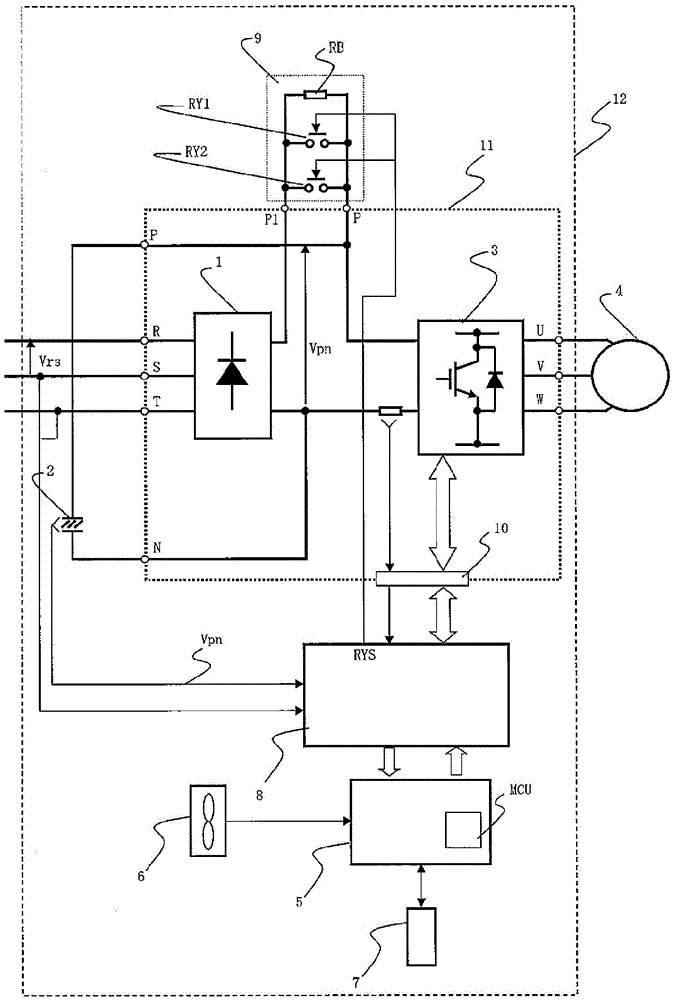
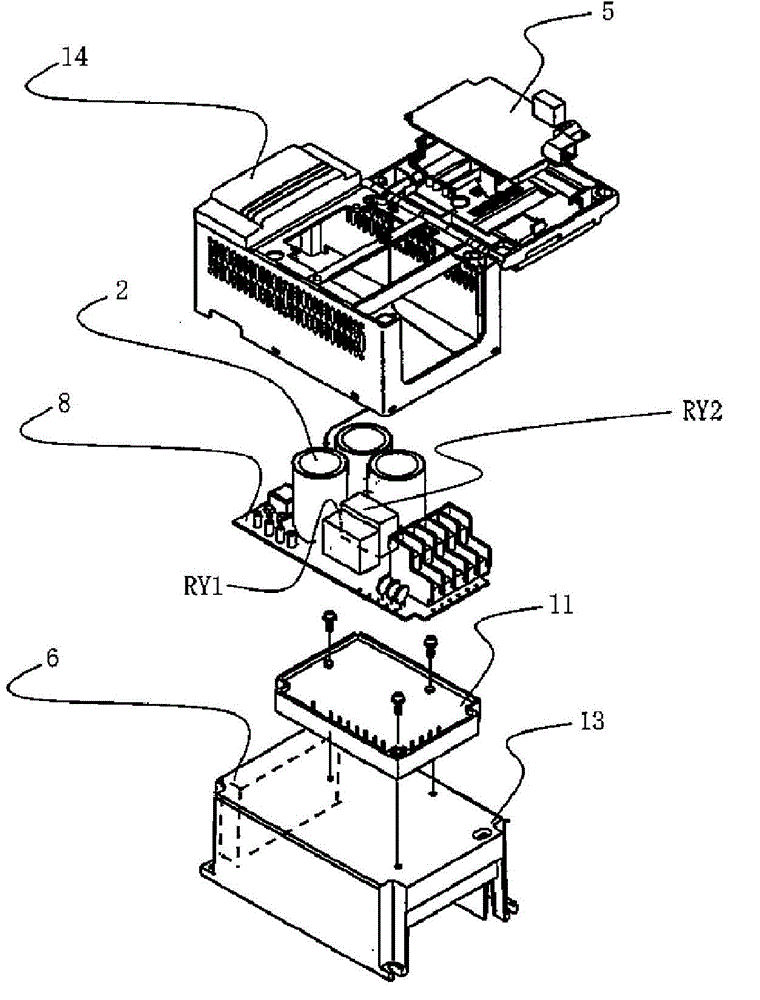
[0057] figure 1 A configuration diagram of a main circuit of the power conversion device 12 of the present embodiment is shown. 1 is a rectifier for converting AC power to DC power, 2 is a smoothing capacitor, 3 is an inverter for converting DC power to AC power of an arbitrary frequency, and 4 is an AC motor. 6 is a cooling fan for cooling the power semiconductor module 11 having the rectifier 1 and the inverter 3 .

[0058] 7 is a digital operation panel for setting and changing various control data of the power conversion device 12 and displaying abnormalities. The MCU, which is a microcomputer mounted in the control circuit 5 , performs calculations based on information stored in a storage unit storing various control data, and ...

Embodiment 2

[0085] Fig. 6 is an example of a copper foil pattern on a substrate.

[0086] 6( a ) and ( b ) show enlarged parts where the relays are mounted among the components constituting the drive circuit 8 , and the bold black lines show copper foil patterns wired on the substrate, and current flows through the foil foil patterns.

[0087] An example is shown in which the lead terminals of the relays RY1 and RY2 are soldered through through holes provided on the substrate. Here, FIG. 6( a ) is an example of a copper foil pattern in which the distribution of the current flowing through the relays RY1 and RY2 connected in parallel is unbalanced.

[0088] The current I flowing through the relays RY1 and RY2 is inversely proportional to the impedance from the inflow point to the outflow point, that is, the wiring length of the copper foil pattern. If the cross-sectional area of ​​the copper foil pattern is the same, the longer the wiring length, the higher the impedance and the smaller t...


PUM


Abstract

The invention provides a power conversion device for outputting AC power having variable voltage and variable frequency. The power conversion device comprises a forward converter for rectifying and converting AC voltage of an AC power source into DC voltage, a DC intermediate circuit having a smoothing capacitor for smoothing the DC voltage of the forward converter, a current-limiting circuit for suppressing a charge current to the smoothing capacitor of the DC intermediate circuit, a voltage detection circuit for detecting the voltage of the DC intermediate circuit, and a reverse converter for converting the DC voltage of the forward converter into AC voltage. A plurality of relays are connected in parallel to a resistor of the current-limiting circuit, and the plurality of relays are switched on when the rate of change of the voltage detection value of the DC intermediate circuit is equal to or less than a value set in advance.

Description

technical field [0001] The present invention relates to a power conversion device in which a plurality of relays of the same capacity are connected in parallel in a surge prevention and suppression circuit. Background technique [0002] Power conversion devices are widely used in industry and in home appliances as speed control devices for electric motors. The voltage source inverter, which is currently the mainstream power conversion device, converts the AC voltage into DC with a rectifier, smoothes it with a large-capacity electrolytic capacitor located in the DC intermediate circuit, and converts it into an AC voltage of any frequency again by the inverter. . [0003] A surge prevention circuit is provided for the purpose of protecting the rectifier diodes constituting the rectifier from the large charging current to the electrolytic capacitor in the DC intermediate circuit. The surge protection circuit is usually connected with a current-suppressing resistor and a rela...

Claims


Application Information

Patent Timeline
Patent Type & Authority Applications(China)
IPC IPC(8): H02H9/02H02H3/05H02M5/44H02M7/06H02M7/48
CPCH02H9/002H02P29/028H02M7/48H02H9/02H02H3/05H02M7/06H02J3/01H02P29/032
Inventor 井堀敏平贺正宏广田雅之荒尾祐介田中良
Owner HITACHI IND EQUIP SYST CO LTD
Why Eureka
Try Eureka