Stirring feeding trolley

A locomotive and feeder technology, applied in the field of mixing and feeding vehicles, can solve the problems of difficult control of processing accuracy, insufficient power output, low feeding efficiency, etc., and meet the requirements of favorable feeding efficiency, stable discharge movement, and coaxiality. low effect

Inactive Publication Date: 2014-10-08
SHIHEZI DEV ZONE SHIDA RUITUO MACHINERY EQUIP +1
View PDF10 Cites 4 Cited by
  • Summary
  • Abstract
  • Description
  • Claims
  • Application Information

AI Technical Summary

Problems solved by technology

[0007] The purpose of the present invention is to overcome the problems of difficulty in controlling the processing accuracy of the parts of the power structure of the existing feeding equipment, serious wear of the parts during the working process, insufficient power output, uneven material spreading and low feeding efficiency, and provide a feeding equipment that can High-efficiency spreading feeding and evenly spreading feeding truck

Method used


Image

  • Stirring feeding trolley
  • Stirring feeding trolley
  • Stirring feeding trolley

Examples


Embodiment

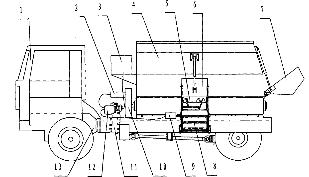
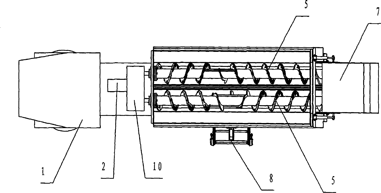
[0017] Embodiment: refer to attached Figure 1~3 , including a power locomotive 1, the power locomotive 1 is provided with a feed box 4, a pair of auger 5 for stirring feed is provided in the feed box 4, a feed hopper 7 is provided at the rear of the feed box 4, and a feed hopper 7 is provided at one side of the feed box 4. There is a discharge port, the discharge port is provided with a discharge port baffle 6, and a discharge hopper 8 is arranged under the discharge port baffle, and a sandwich force is provided between the engine 13 of the power locomotive 1 and the rear axle drive shaft 11, a hydraulic pump 12 is provided on the sandwich power take-off 11, a reduction box 10 is provided at one end of the auger 5, a hydraulic motor A2 is provided on the reduction box 10, and a hydraulic motor B9 is provided on one side of the discharge hopper 8 to obtain power. The material box 4 is provided with a hydraulic oil tank 3, and the hydraulic oil tank 3 stores the hydraulic oil r...


PUM


Abstract

The invention relates to a stirring feeding trolley which is characterized by comprising a power vehicle, wherein a feed box is arranged on the power vehicle. The stirring feeding trolley is characterized in that a pair of packing augers for stirring feed is arranged inside the feed box; a feeding funnel is arranged at the rear part of the feed box; a discharge hole is formed in one side of the feed box; a discharge hole baffle is arranged on the discharge hole; a discharge funnel is arranged below the discharge hole baffle; a sandwiched power taker is arranged between an engine of the power vehicle and a rear axle driving shaft; a hydraulic pump is arranged on the sandwiched power taker; a reduction gearbox is arranged at one ends of the packing augers; a hydraulic motor A is arranged on the reduction gearbox; a hydraulic motor B is arranged on the side of the discharge funnel; a hydraulic oil tank is arranged on the feed box. Compared with the prior art, the stirring feeding trolley solves the problems that the processing precision of components of a power structure of a conventional feeding device is difficult to control, the components are severely abraded in the working process, the power output is not sufficient, the feed cannot be uniformly scattered, and the feeding efficiency is low, and is a stirring feeding trolley which is high in efficiency in scattering and feeding and uniform in scattering the feed.

Description

technical field [0001] The invention relates to a modern animal husbandry mutton sheep feeding machine, in particular to a stirring feeding vehicle. Background technique [0002] At present, with the rapid development of domestic animal husbandry, in order to ensure the health of ruminants such as cattle and sheep, improve feed utilization and breeding benefits, all pastures are now promoting the application of advanced total mixed ration feeding technology (TMR mixed feeding technology) ). The feeding method is: according to the nutritional needs of ruminant animals, mix fine roughage and various additives in an appropriate proportion with a feeding machine, and then feed ruminant animals ad libitum. According to statistics, the existing feeding equipment in the ranch takes power from the power output shaft of the gearbox, and the structure is to take power through two gear half shafts through the gear sleeve. This power take-off method has the following disadvantages : ...

Claims


Application Information

Patent Timeline
Patent Type & Authority Applications(China)
IPC IPC(8): A01K5/02
Inventor 李景彬坎杂李成松郭庆贺王曌鹏尚凤娇田绪顺赵毅兵
Owner SHIHEZI DEV ZONE SHIDA RUITUO MACHINERY EQUIP
Why Eureka
Try Eureka