Self-cooling technology for machined twist drill and machining method for machined twist drill

A processing method, twist drill technology, applied in twist drills, metal processing equipment, parts of boring machines/drilling machines, etc., can solve problems such as inability to achieve cooling effect, twist drills are not durable, and the hardness of the cutter head is reduced, so as to save resources , Improve efficiency and reduce cutting resistance

Inactive Publication Date: 2014-10-08
李仕清
View PDF5 Cites 0 Cited by
  • Summary
  • Abstract
  • Description
  • Claims
  • Application Information

AI Technical Summary

Problems solved by technology

[0002] At present, the twist drill used in mechanical processing is composed of chisel edge, cutting edge, helical minor cutting edge, and side edge. The cutting edge and helical minor cutting edge are roughly in a single structure, with poor centering structure and protruding to the outside of the helical surface. Parts are easy to break, these twist drills are extremely undurable, especially when drilling and milling workpieces with high hardness, a large amount of heat is generated, resulting in a decrease in the hardness of the cutter head, resulting in wear of the cutter head, and the cooling technology becomes the bottleneck of the tool use , it is difficult to inject the coolant directly into the cutting place with ordinary technology, and the ideal cooling effect cannot be achieved.

Method used


Image

  • Self-cooling technology for machined twist drill and machining method for machined twist drill
  • Self-cooling technology for machined twist drill and machining method for machined twist drill
  • Self-cooling technology for machined twist drill and machining method for machined twist drill

Examples


Embodiment approach 1

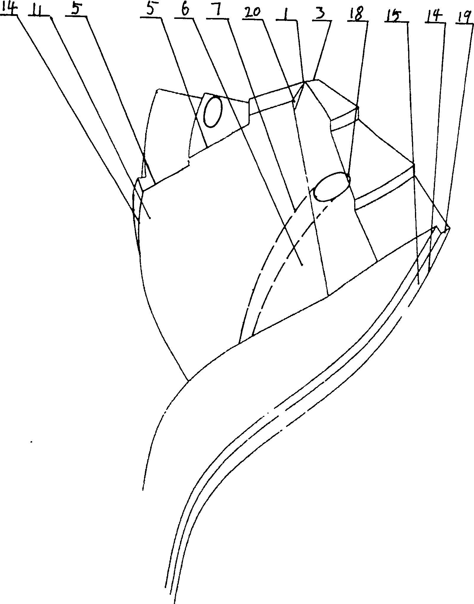
[0036] Such as figure 1 , Figure 7-Figure 10 , Figure 11-Figure 14 As shown, the self-cooling technology and processing method of the machine-added twist drill of the first embodiment of the present invention mainly relate to the machine-added twist drill for mechanical processing, and the self-cooling technology of the machine-added twist drill of the first embodiment of the present invention Cooling technology and processing method thereof, mainly relate to machine-added twist drills for mechanical processing, wherein, Figure 7 The drill point in the axial center is not chamfered, so the chisel edge is larger and the cutting resistance is also larger. Figure 8 Although the drill point in the axial center is chamfered, there is still a reduced chisel edge, and the cutting resistance is relatively Figure 7 reduced a lot, Figure 9-Figure 10 After chamfering, the drill point in the axial center has become a sharp edge without a chisel edge, and the cutting resistance i...

Embodiment approach 2

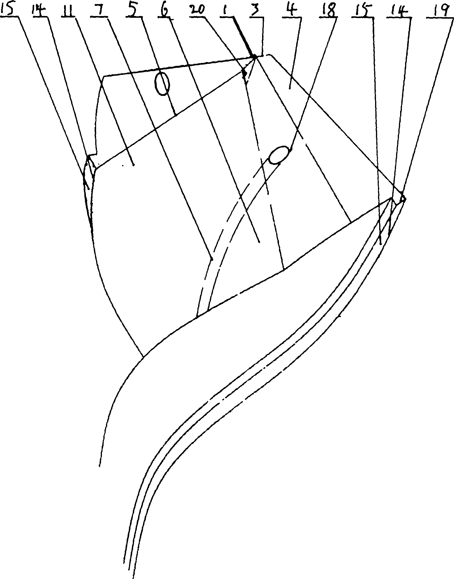
[0040] Such as figure 2 , Figure 6 , Figure 7-Figure 10 ,picture- Figure 14 As shown in Embodiment 2, the self-cooling technology and processing method of the machine-added twist drill of the second embodiment of the present invention, on the basis of the first embodiment, the present invention is a step-shaped protrusion on the rear cutting surface 4 At least one level of stepped composite rear cutting surface 4 is provided, and the stepped composite rear cutting surface 4 intersects with the helical cutting surface 11 to form a stepped composite cutting edge 5 .

[0041] The step-like setting on the rear cutting surface 4 not only improves the cutting stability of the twist drill but also improves the efficiency, reduces the cost and saves resources.

[0042] According to the above structure, it has been proved that the effect of cooling the tool from the cutting place by the coolant is far greater than that achieved by flowing downward from the top. On the one hand,...

Embodiment approach 3

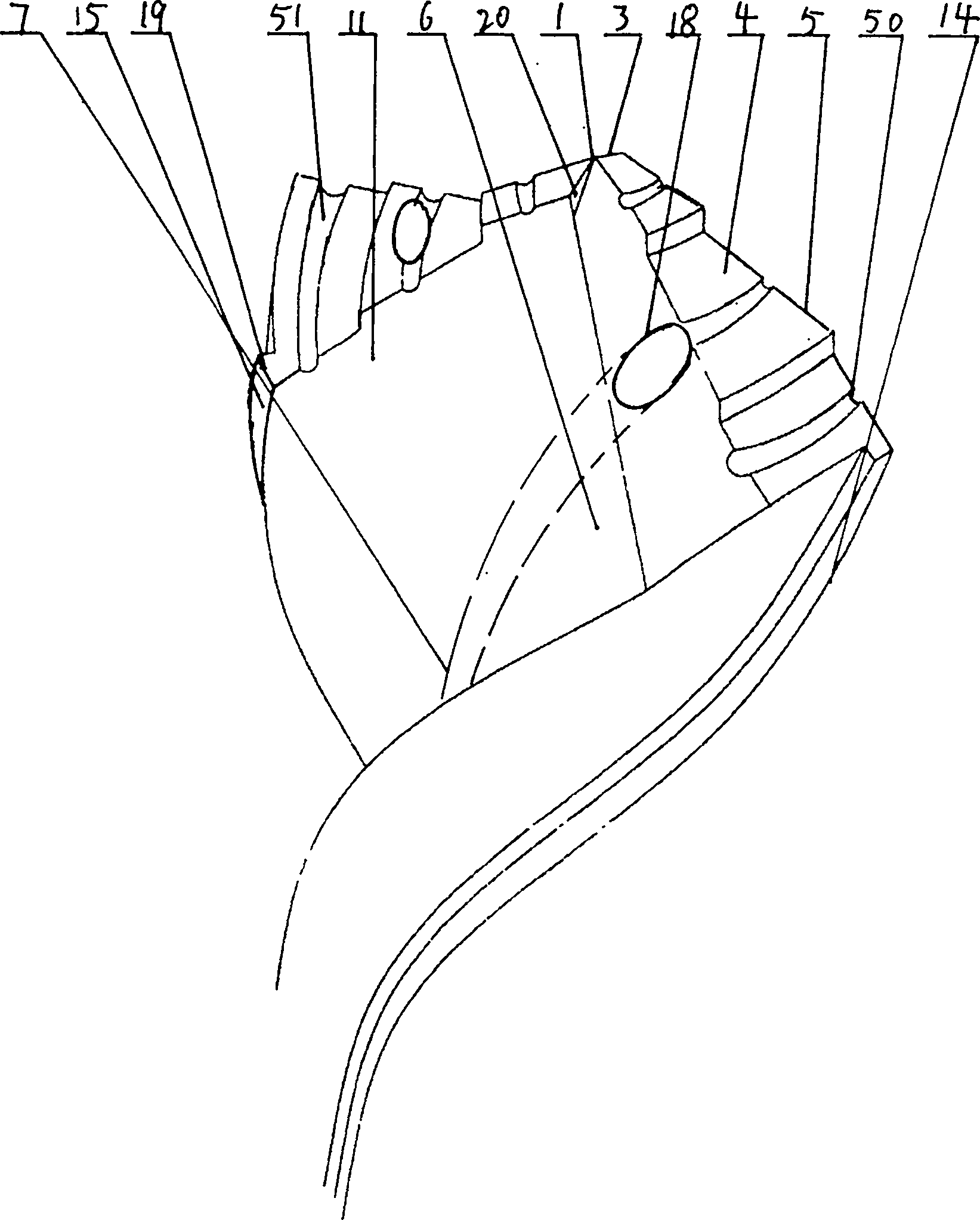
[0044] Such as image 3 , Figure 7-Figure 10 ,picture- Figure 14 As shown, the self-cooling technology and processing method of the machine-added twist drill of the third embodiment of the present invention, on the basis of the first-second embodiment, the present invention is mainly provided with at least one notch on the cutting edge 5 The edge 50 extends toward the rear cutting surface 4 to form a groove 51 .

[0045] By arranging the notch edge 50 on the cutting edge 5, the cutting resistance of the cutting edge 5 is broken down, the cutting efficiency is greatly improved, the cost is reduced, and resources are saved.

[0046] According to the above structure, it has been proved that the effect of cooling the tool from the cutting place by the coolant is far greater than that achieved by flowing downward from the top. On the one hand, the waste chips cut by the tool also prevent the coolant from reaching the cutting place effectively, but the way of sending the coolan...


PUM


Abstract

The invention provides a self-cooling technology for a machined twist drill and a machining method of the machined twist drill, and mainly relates to a machined twist drill. The machined twist drill is characterized in that a spiral secondary cutting blade is arranged on each spiral strip; a spiral secondary cutting face is formed along the outer side of the spiral secondary cutting blade; a spiral cutting face is formed in the front of the spiral secondary cutting blade in the cutting direction; the surface at the top of the front end of the spiral cutting face of the spiral strip at the front end in the axial center of the cutter head is a rear cutting face; the spiral cutting face is intersected with the rear cutting face to form a cutting blade; the included angle between the cutting blade and the spiral secondary cutting blade is set to be a flat blade, an arc-shaped blade or an inclined blade; a notch blade or a trapezoidal blade is arranged on the inner side of the flat blade, the arc-shaped blade or the inclined blade; a drill point or a stepped drill point is convexly arranged in the center of the cutting blade; the surface of the back side opposite to the spiral cutting face in the rotation direction of the machined twist drill is a rear spiral face; at least one spiral groove is formed in a rear spiral face, or spiral platforms are machined on the two sides of the spiral groove, or a water pipe is arranged in the spiral groove, or spiral sealing faces are arranged or welded on the spiral platforms, the shank portion of the top end of the spiral groove or the shank portion of the top end of the spiral platforms is provided with a cooling hole communicated with the spiral groove or the water pipe, and the top end of the shank portion or the shank is provided with a connecting port communicated with the outside.

Description

Technical field: [0001] The invention relates to a self-cooling technology and a processing method of a machine-added twist drill, which are used in drilling machine processing and fitter maintenance. Background technique: [0002] At present, the twist drill used in mechanical processing is composed of chisel edge, cutting edge, helical minor cutting edge, and side edge. The cutting edge and helical minor cutting edge are roughly in a single structure, with poor centering structure and protruding to the outside of the helical surface. Parts are easy to break, these twist drills are extremely undurable, especially when drilling and milling workpieces with high hardness, a large amount of heat is generated, resulting in a decrease in the hardness of the cutter head, resulting in wear of the cutter head, and the cooling technology becomes the bottleneck of the tool use , It is difficult to inject the coolant directly into the cutting place with ordinary technology, and the ide...

Claims


Application Information

Patent Timeline
Patent Type & Authority Applications(China)
IPC IPC(8): B23B51/02B23B51/06
CPCB23B51/02B23B51/0027B23B51/06B23B2251/08B23B2251/12B23B2251/14
Inventor 李仕清
Owner 李仕清
Why Eureka
Try Eureka