
Abrasive belt grinding and polishing device

A polishing device and abrasive belt grinding technology, which is applied in the direction of abrasive belt grinders, grinding/polishing equipment, grinding machines, etc., can solve the problems of inability to rotate quickly, low efficiency, etc., and achieve the effect of improving the quality of grinding and polishing

Active Publication Date: 2014-10-08
CHONGQING UNIV +1
View PDF9 Cites 22 Cited by
  • Summary
  • Abstract
  • Description
  • Claims
  • Application Information

AI Technical Summary

Problems solved by technology

[0005] However, the results of the above research have not yet formed a good abrasive belt grinding and polishing device to deal with the grinding and polishing of workpieces with complex surfaces and special-shaped structures represented by aero-engine blades, and there is no special abrasive belt grinding and polishing for processing such workpieces in China device, the demand for longitudinal grinding of aeroengine blades to improve their mechanical properties such as fatigue strength has not yet been met
From a larger perspective, for some special parts, when they cannot be rotated quickly during processing and cannot be ground with high-speed moving tools, at this stage only low-efficiency manual grinding can be carried out.

Method used


Image

  • Abrasive belt grinding and polishing device
  • Abrasive belt grinding and polishing device
  • Abrasive belt grinding and polishing device

Examples


Embodiment Construction

[0023] The present invention will be further described below in conjunction with the accompanying drawings and specific embodiments.

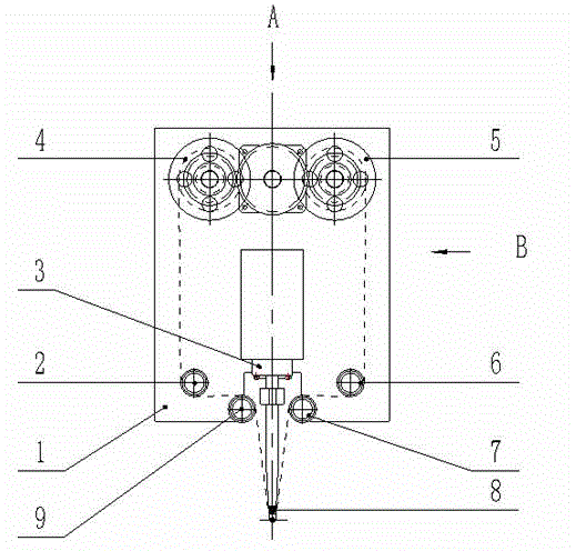
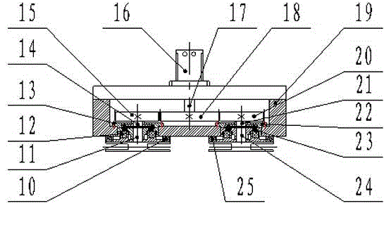
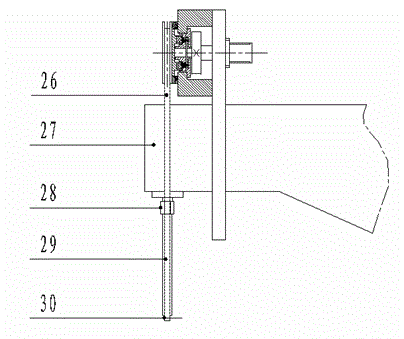
[0024] see Figure 1 ~ Figure 4 Abrasive belt grinding and polishing device includes a reel mounting plate 19, an unwinding wheel 4, a rewinding wheel 5, a tensioning mechanism and a driving mechanism.

[0025] The unwinding wheel 4 and the winding wheel 5 are arranged symmetrically above the reel mounting plate 19 , and the reel mounting plate is installed on the grinding head mounting plate 1 . The tensioning mechanism includes a transition wheel, a contact wheel 30 , a contact rod 29 , a shaft sleeve 28 and a displacement shaft 3 . The transition wheel is an even number of more than two, and the transition wheel is arranged symmetrically below the reel mounting plate 19 . The contact wheel 30 is installed on the lower end of the contact rod 29, the upper end of the contact rod 29 is connected with the lower end of the axle sleeve 28, the u...


PUM


Abstract

The invention discloses an abrasive belt grinding and polishing device. The abrasive belt grinding and polishing device comprises a mounting plate, an unwinding roller, a winding roller, a tensioning mechanism and a driving mechanism. The driving mechanism comprises a servo motor, a driving gear, driven gears, driven gear transmission shafts and roller shafts. The driving gear is mounted on an output shaft of the servo motor. The driven gears are mounted at one end of the driven gear transmission shaft on one side of the driving gear and one end of the driven gear transmission shaft on the other side of the driving gear respectively and are meshed with the driving gear. The unwinding roller is mounted at one end of the corresponding roller shaft. The winding roller is mounted at one end of the corresponding roller shaft. The other ends of the roller shafts are connected with the other ends of the corresponding driven gear transmission shafts through electromagnetic clutches. The tensioning mechanism is composed of friction disks, transition wheels and the like. The rollers are controlled through engagement and disengagement of the electromagnetic clutches arranged between the roller shafts of the rollers and a driving shaft, so that active belt winding or passive belt unwinding is achieved; the friction disks on the end faces of the rollers can apply friction force to the rollers subjected to passive unwinding so as to ensure that a grinding and polishing belt has enough tensile force in the machining process and improve the grinding and polishing quality.

Description

technical field [0001] The invention belongs to the technical field of abrasive belt grinding, and in particular relates to an abrasive belt grinding and polishing device. Background technique [0002] Abrasive belt grinding technology is a technology that uses the abrasive belt for grinding movement as an abrasive tool to grind and polish the surface of the workpiece. It is an elastic processing and has many incomparable advantages compared to other processing methods. On the one hand, it has an irreplaceable role. With the rapid development of abrasive belt grinding technology and devices, abrasive belt grinding and polishing machine tools have developed into a finishing equipment with high processing efficiency, strong adaptability, wide application range, low cost of use, and safe and convenient operation. Especially for the processing of thin-walled structural parts with complex curved surfaces such as aero-engine blades, the grinding and polishing of small-sized compl...

Claims


Application Information

Patent Timeline
Patent Type & Authority Applications(China)
IPC IPC(8): B24B21/16B24B21/18B24B21/20
CPCB24B21/16B24B21/18B24B21/20
Inventor 黄云肖贵坚潘复生杨俊峰陈亚雄刘颖
Owner CHONGQING UNIV
Learn More