mud scraper for drilling tool

A mud scraper and drilling tool technology, which is applied in the direction of cleaning equipment, earthwork drilling, wellbore/well parts, etc., can solve the problems of affecting the work of drill pipes, affecting production safety, and not being able to fit, so as to save labor time, The effect of reducing labor intensity and improving work efficiency

Active Publication Date: 2016-06-01
JIANGSU YANGZHOU HELI RUBBER PROD
View PDF3 Cites 0 Cited by
  • Summary
  • Abstract
  • Description
  • Claims
  • Application Information

AI Technical Summary

Problems solved by technology

[0002] During drilling operations in oil fields, mud adheres to the drill pipe, which affects the work of the drill pipe. At the same time, if the mud on the drill pipe is taken out to the drilling platform, it will seriously affect the working environment, such as causing the site to be muddy and wet. It is slippery, inconvenient for construction, and affects production safety; therefore, it is very necessary to remove the mud on the drill pipe; however, manual removal of mud increases labor intensity
[0003] In the prior art, the drill pipe mud scraper needs to be adapted to the corresponding drill pipe during work, so that when changing drill pipes of different specifications, the drill pipe mud scraper needs to be replaced and adjusted, which increases the labor time and reduces the working time. Reliability; there are also adaptive drill pipe mud scrapers, such as Figure 16 As shown, during normal operation, there is close contact between the mud scraper and the drill pipe 131; however, as Figure 17-18 As shown, in operation, as the diameter of the drill pipe (drill pipe 2 132 and drill pipe 3 133) becomes smaller, the adaptive effect of the drill pipe mud scraper is very poor, due to the change and deformation of the curvature of the arc-shaped rubber flap Features, the phenomenon that the middle fits and the two ends cannot fit, which reduces the effect of drill pipe mud scraping

Method used


Image

  • mud scraper for drilling tool
  • mud scraper for drilling tool
  • mud scraper for drilling tool

Examples


Embodiment Construction

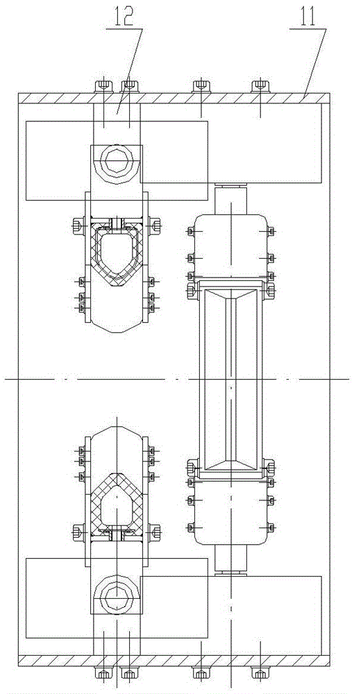
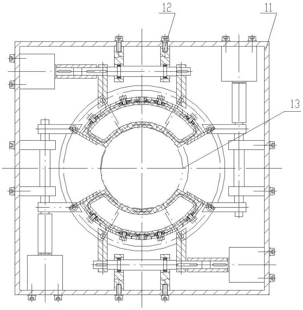
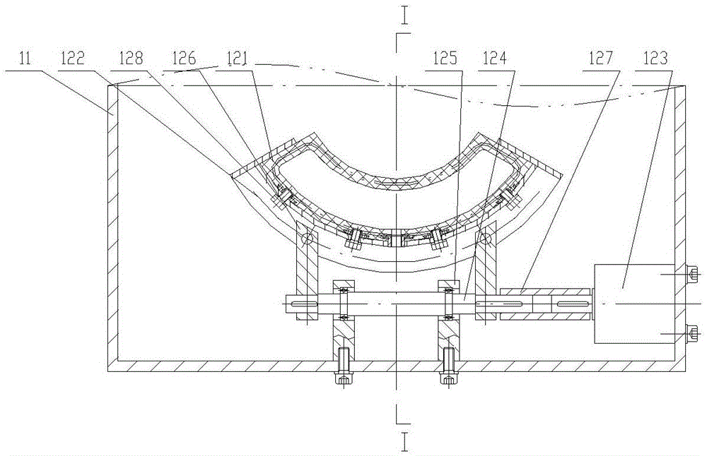
[0045] The present invention as Figure 1-15 As shown, it includes a cylinder body 11 and several groups of mud scraping assemblies 12, and several groups of the mud scraping assemblies 12 are arranged on the inner wall of the cylinder body 11,

[0046] The mud scraping assembly 12 includes an inflatable mud scraping flap 121, a steel ring 122, a swing cylinder 123, a rotating shaft 124, a fixed seat 125, a swing rod 126 and an air source,

[0047] The inflatable mud scraper 121 is arc-shaped and is used to cover the drill pipe 13. The inflatable mud scraper 121 is fixedly connected to the steel ring 122, and the air hole 1211 is provided on the inflatable mud scraper 121. And the drill pipe compensation mechanism, the air source is connected to the air hole 1211; so that the degree of fit between the inflatable mud scraping flap and the drill pipe 13 (that is, the achieved mud scraping effect) is adjusted by the size of the air pressure.

[0048] The swing cylinder 123 is fi...


PUM


Abstract

The invention provides a sludge scraper for a well drilling tool. The sludge scraper is simple in structure and convenient to operate, and effectively improves the work efficiency and the reliability of sludge scraping. The sludge scraper comprises a cylinder body and a plurality of sludge scraping assemblies. The sludge scraping assemblies are uniformly distributed on the inner wall of the cylinder body. Each sludge scraping assembly comprises an inflation sludge scraping petal, a steel ring, a swing air cylinder, a rotating shaft, a fixed base, a swing rod and an air source. The inflation sludge scraping petals are of arc shapes, and are used for wrapping drill rods, fixedly connected to the steel rings, and provided with air holes and drill rod compensation mechanisms. The air sources are communicated with the air holes. The fixed bases are fixedly connected to the inner wall of the cylinder body and provided with rotating holes. The rotating shafts are movably connected into the rotating holes of the fixed base. The swing rods are connected between the steel rings and the rotating shafts. The sludge scraper improves the work efficiency and relieves the labor intensity of oil workers.

Description

technical field [0001] The invention relates to a drill pipe mud scraper in drilling operations. Background technique [0002] During drilling operations in oil fields, mud adheres to the drill pipe, which affects the work of the drill pipe. At the same time, if the mud on the drill pipe is taken out to the drilling platform, it will seriously affect the working environment, such as causing the site to be muddy and wet. It is slippery, inconvenient for construction, and affects production safety; therefore, it is very necessary to remove the mud on the drill pipe; however, manual removal of mud increases the labor intensity. [0003] In the prior art, the drill pipe mud scraper needs to be adapted to the corresponding drill pipe during work, so that when changing drill pipes of different specifications, the drill pipe mud scraper needs to be replaced and adjusted, which increases the labor time and reduces the working time. Reliability; there are also adaptive drill pipe mu...

Claims


Application Information

Patent Timeline
Patent Type & Authority Patents(China)
IPC IPC(8): E21B37/02
Inventor 袁建东朱克斌高元翁兰芳姚玉娟
Owner JIANGSU YANGZHOU HELI RUBBER PROD
Why Eureka
Try Eureka