Silencer of high-pressure blower

A high-pressure blower and muffler technology, which is applied to the components of the pumping device for elastic fluids, mechanical equipment, machines/engines, etc. performance effect

Active Publication Date: 2014-10-08
NINGBO SHENGHONG MACHINERY EQUIP
View PDF7 Cites 4 Cited by
  • Summary
  • Abstract
  • Description
  • Claims
  • Application Information

AI Technical Summary

Problems solved by technology

Although this invention changes the original single inner tube silencer into multi-inner tube silencer, increases the contact area between the inner tube and the soft sound-a

Method used


Image

  • Silencer of high-pressure blower
  • Silencer of high-pressure blower
  • Silencer of high-pressure blower

Examples


Embodiment 1

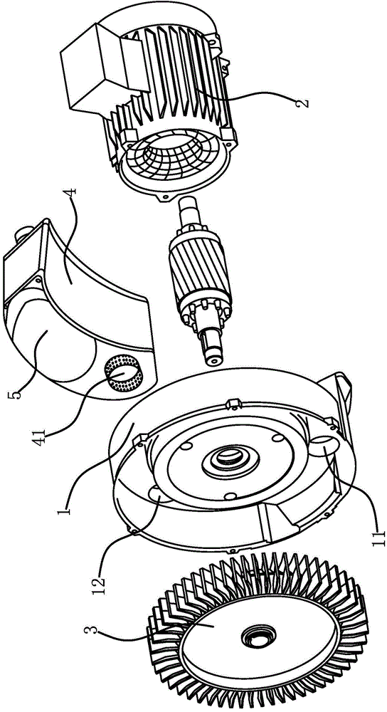
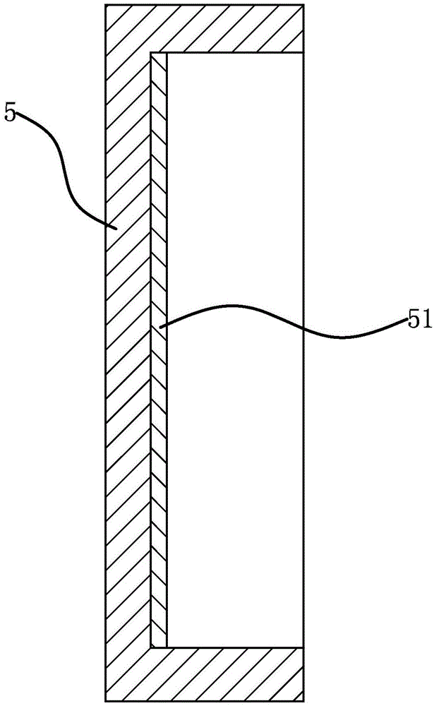
[0038] The raw materials were weighed according to the components and parts by weight of the sound-absorbing coating in Example 1 in Table 1. Under the condition of stirring, dissolve the dispersant, preservative, filler and polysiloxane in 4 parts of water and stir well. Then add acrylic resin, film-forming aid and 4 parts of water under stirring condition and stir evenly. Then divide the weighed hollow plastic balls into 5 equal parts and add them in 5 times. After each addition, they need to be stirred evenly before adding the remaining hollow plastic balls. Finally, add the remaining 4 parts of water and stir evenly to obtain the sound-absorbing coating. Finally, put the prepared sound-absorbing paint into the hopper of the spray gun, move the spray gun in one direction, and spray on the inner surface of the cover plate 5 step by step for 4 times, and dry to obtain the sound-absorbing coating 51 .

Embodiment 2

[0040] The raw materials were weighed according to the components and parts by weight of the sound-absorbing coating in Example 2 in Table 1. Under the condition of stirring, dissolve the dispersant, preservative, filler and polysiloxane in 6 parts of water and stir evenly. Then add acrylic resin, coalescent and 6 parts of water under stirring condition and stir evenly. Then divide the weighed hollow plastic balls into 3 equal parts and add them in 3 times. After each addition, they need to be stirred evenly before adding the remaining hollow plastic balls. Finally, add the remaining 6 parts of water and stir evenly to obtain the sound-absorbing coating. Finally, put the prepared sound-absorbing paint into the hopper of the spray gun, move the spray gun in one direction, and spray on the inner surface of the cover plate 5 step by step twice, and dry to obtain the sound-absorbing coating 51 .

Embodiment 3

[0042] The raw materials were weighed according to the components and parts by weight of the sound-absorbing coating in Example 3 in Table 1. Under the condition of stirring, dissolve the dispersant, preservative, filler and polysiloxane in 8 parts of water and stir evenly. Then add acrylic resin, film-forming aid and 8 parts of water under stirring condition and stir evenly. Then divide the weighed hollow plastic balls into 4 equal parts and add in 4 times. After each addition, it needs to be stirred evenly before adding the remaining hollow plastic balls. Finally, add the remaining 8 parts of water and stir evenly to obtain the sound-absorbing coating. Finally, put the prepared sound-absorbing paint into the hopper of the spray gun, move the spray gun in one direction, and gradually spray five times on the inner surface of the cover plate 5, and dry to obtain the sound-absorbing coating 51.


PUM


Abstract

The invention relates to a silencer of a high-pressure blower. The silencer comprises a wind tub and a motor, wherein the output shaft of the motor extends into the wind tub, and the extending-in end of the output shaft is fixedly connected with a wind blade; a wind inlet and a wind outlet are formed in the wind tub; the silencer comprises a strip-shaped box body, a wind intake hole is formed in the end surface of one end of the box body, and a wind exhaust hole is formed in the end surface of the other end of the box body; the wind intake hole is communicated with the wind outlet in the wind tub; a plurality of strip-shaped partition boards are fixedly connected to the inner part of the box body, and the box is divided into a plurality of chambers through the partition boards; every two adjacent chambers are communicated, and the wind intake hole is communicated with the chamber in one side of the box body; the wind exhaust hole is communicated with the chamber in the other side of the box body; both ends of the box body are respectively and fixedly connected with one cover plate, and the inside surfaces of the cover plates are fixedly connected with acoustical coatings which are sprayed by anti-noise paint. When air currents generate impact on the partition boards, the inner wall of the box body and the cover plates, noise is absorbed, so that the silencer of the high-pressure blower has a better erasing effect, and the whole quality of the blower is improved.

Description

technical field [0001] The invention relates to a noise reduction device for a high-pressure blower, belonging to the technical field of blower equipment. Background technique [0002] High-pressure blower, also called high-pressure blower, has fan blades installed inside. When the fan blades rotate, due to the centrifugal force, the wind vane makes the gas move forward and outward, thus forming a series of spiral movements. The air accelerates to rotate in a spiral shape and squeezes the gas outside the pump body into the side channel. When it enters the side channel, the gas is compressed and then returns to the impeller blades to accelerate the rotation again. Each impeller blade increases the compression and acceleration. As the rotation progresses, the kinetic energy of the gas increases, making the pressure of the gas passing through the side channel further increase, and finally the gas is squeezed out of the blades and discharged out of the pump body through the outl...

Claims


Application Information

Patent Timeline
IPC IPC(8): F04D29/66C09D133/00C09D5/32
Inventor 陈镇华周政富
Owner NINGBO SHENGHONG MACHINERY EQUIP
Why Eureka
Try Eureka