Heat exchange device of cooling tower

A technology for heat exchange devices and cooling towers, which is applied in the direction of water shower coolers, heat exchanger types, direct contact heat exchangers, etc., and can solve the aggravated load changes in the filling area, uneven water spraying, and uneven wind in the cooling tower Distribution and other issues to achieve the effect of improving cooling efficiency

Active Publication Date: 2014-10-08
GUODIAN LONGYUAN POWER TECH ENG
View PDF5 Cites 14 Cited by
  • Summary
  • Abstract
  • Description
  • Claims
  • Application Information

AI Technical Summary

Problems solved by technology

[0007] However, in reality, the wind in the cooling tower is unevenly distributed. If the water is evenly distributed, the spraying water will be uneven, and heavy water areas, light water areas or no water areas will appear, resulting in the coexistence of excessive wind resistance and air short circuit, resulting in filler The area load changes aggravated, resulting in low cooling efficiency of the cooling tower

Method used


Image

  • Heat exchange device of cooling tower
  • Heat exchange device of cooling tower
  • Heat exchange device of cooling tower

Examples


Embodiment Construction

[0036] In order to make the object, technical solution and advantages of the present invention clearer, the implementation manner of the present invention will be further described in detail below in conjunction with the accompanying drawings.

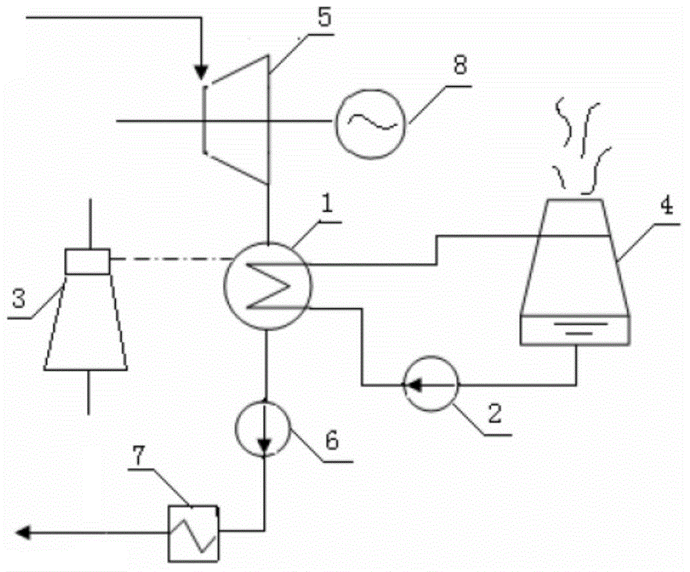
[0037] Cooling tower 4 is a cold end system, with figure 1 The power generation system of the thermal power plant shown as an example is explained. It provides circulating cooling water with the required temperature and flow rate to the condenser 1 to cool the exhausted steam in the main system, and absorbs the latent heat of vaporization of exhausted steam to make it become Condensed water is formed to complete the cycle; in addition, it also provides guarantee for the formation and maintenance of the vacuum of the condenser. The working process of the power generation system is as follows: the steam turbine 5 works under the impetus of external high-temperature and high-pressure steam to drive the generator 8 to generate electricity....


PUM


Abstract

The invention discloses a heat exchange device of a cooling tower. The heat exchange device comprises a splashing mechanism and a filling mechanism, wherein the splashing mechanism comprises a water distribution system and a nozzle cluster; a water inlet and multiple water outlets are formed in the water distribution system; the nozzle cluster comprises a first group of nozzles, a second group of nozzles and a third group of nozzles; a cooling plane formed by the first, second and third groups of nozzles is vertically intersected with the axis of a tower barrel; the cooling plane comprises a central area in which the first group of nozzles are arranged, an inner area in which the second group of nozzles are arranged and a peripheral area in which the third group of nozzles are arranged; the central area, the inner area and the peripheral are all annular and are arranged at the central area, the inner area and the peripheral area along the radial direction of the tower barrel in sequence; the filling mechanism comprises a first area, a second area and a third area which are arranged along the radial direction of the tower barrel in sequence; the first area and the second area are corresponding to the projections of the central area and the inner area in the axial direction of the tower barrel respectively; the spraying density of the first area is smaller than that of the second area. According to the heat exchange device, the cooling efficiency of the cooling tower can be improved.

Description

technical field [0001] The invention belongs to the field of cold end equipment of a power plant, in particular to a heat exchange device of a cooling tower. Background technique [0002] Cooling towers are used to exchange heat between high-temperature circulating water and air in the tower to cool the high-temperature circulating water, and are widely used in power plants. [0003] According to the provisions of the "Energy Saving Evaluation and Energy Audit Manual" of thermal power plants, within the scope of the design permit, every 1.0°C decrease in the temperature of the circulating water cooled by the cooling tower can reduce the heat consumption of the generating set by 0.3-0.5%, and the coal consumption of power generation Can reduce 1.1g / (KWH). Since the heat transfer performance of the cooling tower determines the temperature of the circulating water entering the condenser, it has a vital impact on the safe and economical operation of the unit and even the entire...

Claims


Application Information

Patent Timeline
Patent Type & Authority Applications(China)
IPC IPC(8): F28C1/00F28F25/06F28F25/08
Inventor 闵健刘学民腾东玉张宇严四华田红霞张彤燕赵虎军
Owner GUODIAN LONGYUAN POWER TECH ENG
Why Eureka
Try Eureka