Extruder cleaning pad cooling device and use method thereof

A cooling device and extruder technology, applied in the field of metallurgical equipment, can solve the problems of prolonging the production cycle, affecting the service life, long cooling time, etc., and achieving the effects of reliable and stable torsional power, prolonged service life and high degree of automation

Pending Publication Date: 2019-09-03
CHINA NAT HEAVY MACHINERY RES INSTCO
View PDF13 Cites 0 Cited by
  • Summary
  • Abstract
  • Description
  • Claims
  • Application Information

AI Technical Summary

Problems solved by technology

[0003] The cooling process of the existing cleaning pad is usually completed by manual operation, and two methods are generally used: one is to manually use compressed air to cool the surface of the extrusion pad, the cooling time is longer, and the cooling effect is not obvious; the other is to manually use The cooling water pipe performs rough fluid jet cooling on the surface of the cleaning pad, resulting in waste of water resources, and the uneven cooling process of the surface of the cleaning pad affects its service life
In short, manual operation to complete the cooling process not only has disadvantages such as poor cooling effect and affecting the quality of the cleaning pad, but also wastes manpower and resources, is inefficient, and prolongs the production cycle of the entire equipment

Method used


Image

  • Extruder cleaning pad cooling device and use method thereof
  • Extruder cleaning pad cooling device and use method thereof
  • Extruder cleaning pad cooling device and use method thereof

Examples


Embodiment 1

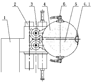
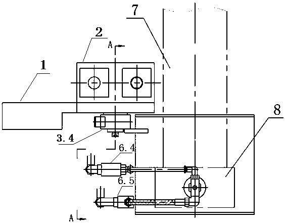
[0027] Such as figure 1 , figure 2 As shown, an extruder cleaning pad cooling device at least includes a cleaning pad 8, and the cleaning pad 8 is fixed on the front end of the cleaning shaft 7, and also includes a fixing seat 1, a power device 2, a transmission device 3, an upper half Cover 4, lower half cover 5 and pressure spray device 6, one side of the fixed seat 1 is provided with a power device 2, and the other side of the fixed seat is provided with a transmission device 3, and the power device 2 and the transmission device 3 relative settings;

[0028] The transmission device 3 includes an output shaft 3.2, a driving gear 3.3, a pin shaft 3.4 and a driven gear 3.5, one end of the output shaft 3.2 passes through the fixed seat 1 and is connected to the power unit 2, and the other end of the output shaft 3.2 is connected to the driving gear 3.3 connection, the driven gear 3.5 is connected with the fixed seat 1 through the pin shaft 3.4, and meshes with the driving ge...

Embodiment 2

[0032] On the basis of the above embodiments, the power device 2 is a double-rack swing cylinder with a magnetic switch, and its function is to use compressed air to drive the output shaft to perform reciprocating rotary motion within a certain angle range. The double-rack swing cylinder can be output with multiple torques to ensure sufficient torsional power, and the output torsional power is reliable and stable, and the transmission efficiency is high; it is installed on the fixed seat by screws, and the structure is reliable.

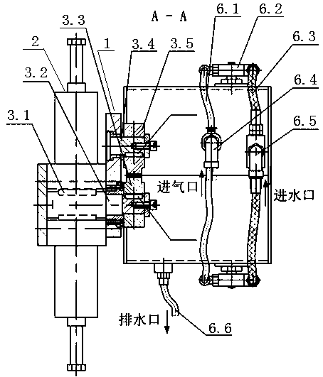
[0033] One end of the output shaft 3.2 passes through the fixed seat 1, and is connected with the power unit 2 through the key one 3.1, the other end of the output shaft 3.2 is connected with the driving gear 3.3 through the key three 3.7, and the pin shaft 3.4 passes through the fixed seat 1, And be connected with driven gear 3.5 by key two 3.6. After assembly, it should be ensured that the center distance between the pin shaft 3.4 and the output sh...

Embodiment 3

[0035] Such as image 3As shown, further, the pressure spray device 6 includes an atomizing nozzle 6.2, an air hose 6.1, an air tee joint 6.4, a water hose 6.3 and a water tee joint 6.5, and the top of the upper half cover 4 is connected to the The bottom of the lower half cover 5 is equipped with atomizing nozzles 6.2 respectively. The left and right sides of the atomizing nozzles 6.2 are air inlets and water inlets respectively. The two passages of the air tee joint 6.4 are connected, the water inlets of the two atomizing nozzles 6.2 are respectively connected with the two passages of the water tee joint 6.5 through the water hose 6.3, and the air tee joint 6.4 is connected to the The other channel of the waterway tee joint 6.5 is used as the total air inlet and water inlet respectively, and is connected with the compressed air station and the cooling water station respectively, so that the two nozzles can be opened and closed synchronously.

[0036] Further, the atomizing ...


PUM


Abstract

The invention provides an extruder cleaning pad cooling device and a use method thereof. The device comprises a fixed base, a power device, a transmission device, an upper half cover, a lower half cover and pressure spray devices, the power device is arranged on one side of the fixed base, the transmission device is arranged on the other side of the fixed base, the power device and the transmission device are oppositely arranged, the transmission device comprises an output shaft, a driving gear, a pin shaft, and a driven gear, one end of the output shaft penetrates through the fixed base to beconnected with the power device, the other end of the output shaft is connected with the driving gear, the driven gear is arranged on the fixed base and is engaged with the driving gear, the upper half cover and lower half cover are fixed to the driven gear and the driving gear correspondingly, through gear engaging rotation, the upper half cover and the lower half cover are driven to be synchronously opened and closed, the top of the upper half cover and the bottom of the lower half cover are provided with the pressure spray devices, a cleaning shaft can drive a cleaning pad to move in or move out of the center position generated when the upper half cover and the lower half cover are in closing state after the upper half cover and the lower half cover are synchronously opened to be in place, and rapid cooling of the cleaning pad is achieved.

Description

technical field [0001] The invention belongs to the technical field of metallurgical equipment, relates to extrusion production and processing equipment, in particular to an extruder cleaning pad cooling device and a use method thereof, which can conveniently and efficiently realize rapid cooling of the extruder cleaning pad. Background technique [0002] Before the extrusion production of the extrusion machine, in order to reduce the deformation resistance during the extrusion process, lubricants such as graphite are often added to the extrusion cylinder, and at the same time, after each extrusion is completed, there are often some metal residues in the extrusion cylinder And oxide skin, etc., so it is necessary to use a cleaning pad to clean the inner wall of the extrusion cylinder in time to ensure the smooth progress of cyclic extrusion. In order to achieve a good cleaning effect, the gap between the outer diameter of the extruder cleaning pad and the inner diameter of t...

Claims


Application Information

Patent Timeline
Patent Type & Authority Applications(China)
IPC IPC(8): B21C29/00
CPCB21C29/003
Inventor 王哲琳权晓惠张立波董晓娟荆云海邱立朋张峻郭永安
Owner CHINA NAT HEAVY MACHINERY RES INSTCO
Why Eureka
Try Eureka