Material complex permittivity testing system and method with perforated short circuit plate

A complex dielectric constant and testing system technology, which is applied in measuring devices, measuring electrical variables, measuring resistance/reactance/impedance, etc., can solve the problems of easy damage of screws, damage of waveguide and short circuit board, inconvenience of sample insertion, etc., to achieve Easy to use, reduce system error, and facilitate the effect of vacuuming

Inactive Publication Date: 2014-10-08
UNIV OF ELECTRONICS SCI & TECH OF CHINA
View PDF7 Cites 20 Cited by
  • Summary
  • Abstract
  • Description
  • Claims
  • Application Information

AI Technical Summary

Problems solved by technology

Based on this method, there are the following points: 1. The short-circuit board needs to be disassembled to take out the sample for each test, which is inconvenient to operate; 2. For high-temperature testing, materials that can withstand high temperatures are used to make waveguides, short-circuit boards and screws. The mechanical properties of these materials are not good, and it may cause damage to the waveguide and short-circuit board after repeated disassembly, which will affect the test, especially the screws are very easy to damage; 3. Since the short-circuit board is close to the waveguide, the size of the sample and the size of the inner wall of the waveguide Rather, an air column will be formed between the sample and the short circuit board every time the sample is placed, which is not convenient for the sample to be placed, and even causes an air layer to form between the sample and the short circuit board, which will greatly affect the test results

Method used


Image

  • Material complex permittivity testing system and method with perforated short circuit plate
  • Material complex permittivity testing system and method with perforated short circuit plate
  • Material complex permittivity testing system and method with perforated short circuit plate

Examples


Embodiment Construction

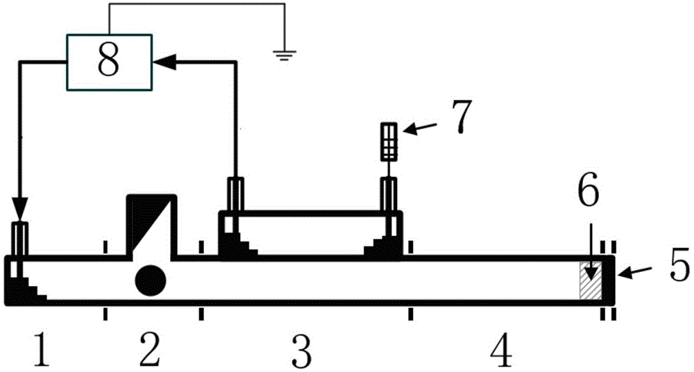
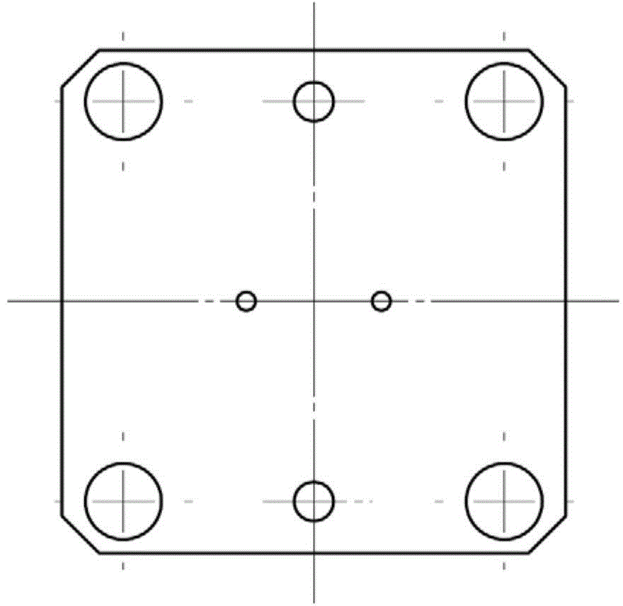
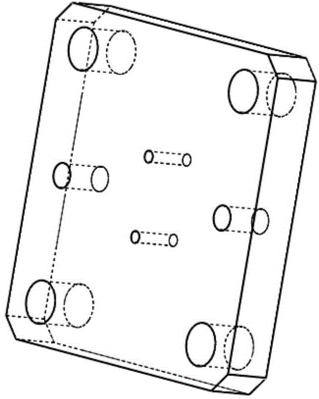
[0019] Material complex permittivity test system with open-hole short-circuit board, such as figure 1 As shown, it includes a sequentially connected coaxial cable to a rectangular waveguide conversion joint 1, an isolator 2, a bidirectional coupler 3, a rectangular waveguide 4 and a short circuit board 5; it also includes a vector network analyzer 8, and the output of the vector network analyzer 8 The test signal of the test signal is connected to the conversion joint 1 from the coaxial cable to the rectangular waveguide through the signal input coaxial cable, and the coupling end output test signal of the bidirectional coupler 3 away from the short circuit board 5 is input to the vector network analyzer 8 through the signal output coaxial cable, The coupling end of the bidirectional coupler 3 close to the short circuit board 5 is connected with a matching load 7; the middle area of ​​the short circuit board 5 has a through hole.

[0020] Further, in the above-mentioned materi...


PUM


Abstract

The invention discloses a material complex permittivity testing system and method with a perforated short circuit plate, and belongs to the technical field of testing of the electromagnetic parameters of microwave or millimeter wave materials. The testing system comprises a coaxial cable-rectangular waveguide adapter, an isolator, a bidirectional coupler, a rectangular waveguide and the perforated short circuit plate, wherein the coaxial cable-rectangular waveguide adapter, the isolator, the bidirectional coupler, the rectangular waveguide and the perforated short circuit plate are connected in sequence. Testing signals output by a vector network analyzer are connected with the coaxial cable-rectangular waveguide adapter through a signal input coaxial cable. Testing signals output by the coupling end, away from the short circuit plate, of the bidirectional coupler are input to the vector network analyzer through a signal output coaxial cable. The coupling end, close to the short circuit plate, of the bidirectional coupler is connected with a matched load. According to the complex permittivity testing system, testing samples can be conveniently taken or put, system errors of a testing system adopting the rectangular waveguide terminal short circuit method are reduced, the testing efficiency is improved, and the service life of the testing system is prolonged.

Description

technical field [0001] The invention belongs to the technical field of electromagnetic parameter testing of microwave and millimeter wave materials, in particular a system and method for testing the complex dielectric constant of microwave dielectric materials based on a terminal short circuit method. Background technique [0002] As an electromagnetic wave transmission medium, microwave dielectric materials have been widely used in aerospace, microwave circuits, communications, missile guidance, electronic countermeasures, stealth technology, biomedicine, remote sensing and telemetry, etc. Therefore, mastering the parameters of microwave dielectric materials for its research and development, production and use has extremely great significance. The terminal short circuit method is to fill the sample of the dielectric material to be tested in the transmission line with the terminal short circuit, and calculate the complex dielectric constant of the sample by testing the compl...

Claims


Application Information

Patent Timeline
Patent Type & Authority Applications(China)
IPC IPC(8): G01R27/26
Inventor 李恩王依超郭高凤
Owner UNIV OF ELECTRONICS SCI & TECH OF CHINA
Why Eureka
Try Eureka