Central vacuumizing impregnation system and control method thereof

A central control system and vacuum pumping technology, which is applied in the direction of drying/impregnating machines, electrical components, electrolytic capacitors, etc., can solve the problems of uneven dipping quality of capacitor cores, low production efficiency, and affecting the dipping quality of capacitor cores, etc.

Inactive Publication Date: 2014-10-08
ZHAOQING BERYL ELECTRONICS TECH
View PDF5 Cites 4 Cited by
  • Summary
  • Abstract
  • Description
  • Claims
  • Application Information

AI Technical Summary

Problems solved by technology

However, in the production process, when workers process a batch of capacitor core packages, they not only need to control the impregnation machine to process the capacitor core packages, but also control the vacuum machine to vacuumize the impregnation machine. The process is cumbersome, and the entire impregnation process relies more on manpower. operation, so the production efficiency is low; in addition, the vacuum degree of the cylinder of the impregnation machine will directly affect the impregnation quality of the capacitor core package. The impregnation quality is uneven

Method used


Image

  • Central vacuumizing impregnation system and control method thereof
  • Central vacuumizing impregnation system and control method thereof
  • Central vacuumizing impregnation system and control method thereof

Examples


Embodiment 1

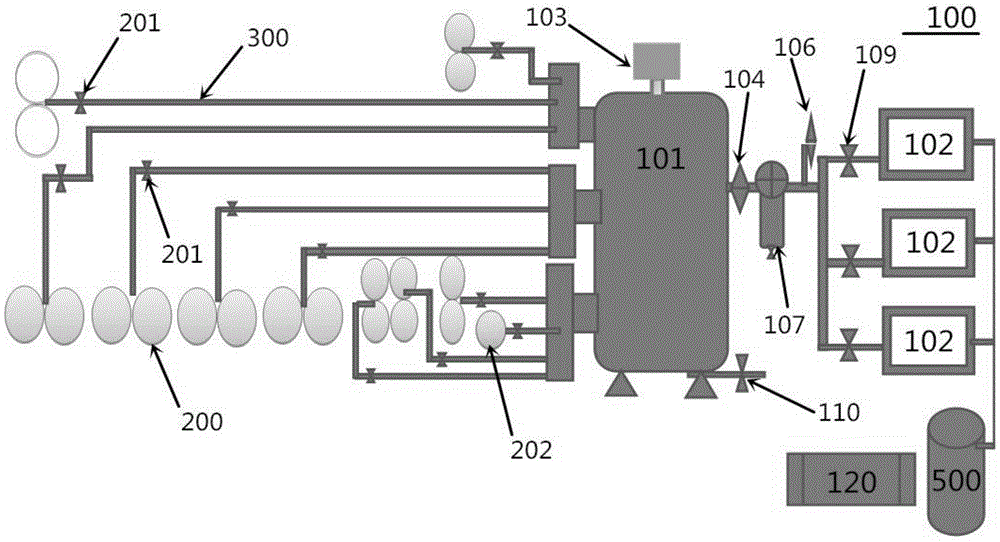
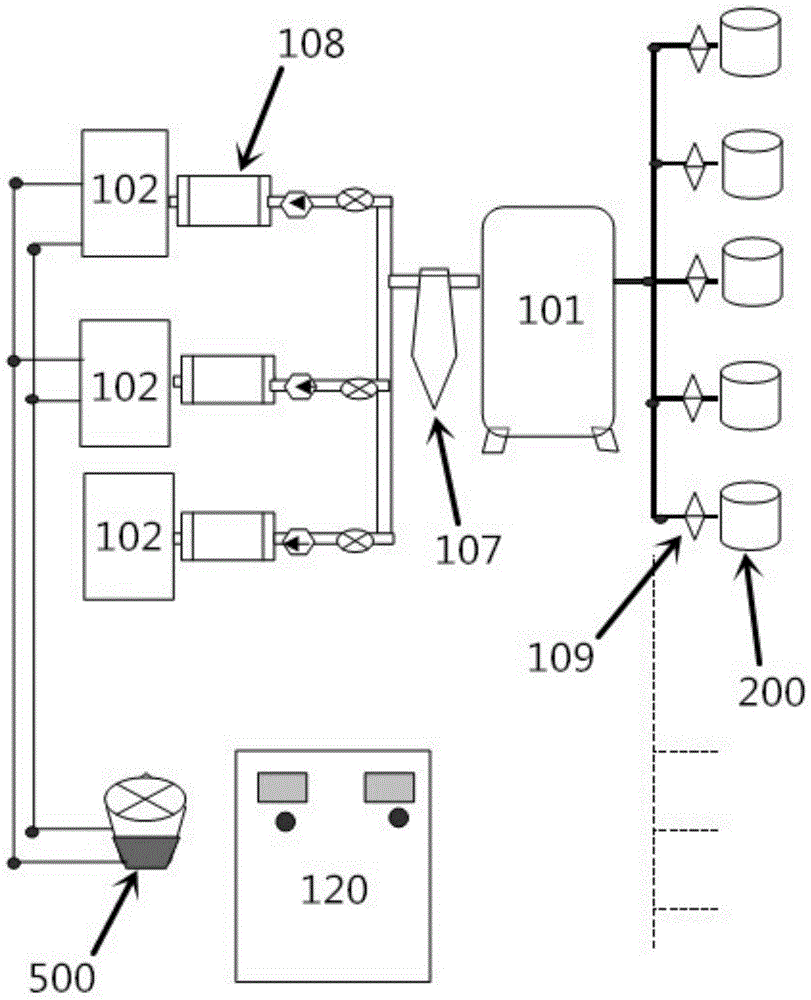
[0029] Such as figure 1 As shown, a central vacuum impregnation system includes a central control system 100 and several impregnation machines 200. The central control system 100 includes a vacuum storage cylinder 101, a vacuum machine 102, an electric control box 120, and a vacuum monitor 103. The electric control box 120 is provided with a PLC control module (not shown in the figure), and the vacuum monitor 103 is installed on the vacuum storage cylinder 101 and can monitor the internal vacuum level of the vacuum storage cylinder 101, specifically the vacuum value or air pressure value. Each impregnation machine 200 is independently connected to the vacuum storage cylinder 101 through pipelines, and the pipelines between each impregnation machine 200 and the vacuum storage cylinder 101 are respectively provided with valves 201 . The vacuum storage cylinder 101 is connected to the suction end of the vacuum machine 102 through a pipeline, and the pipeline between the vacuum st...

Embodiment 2

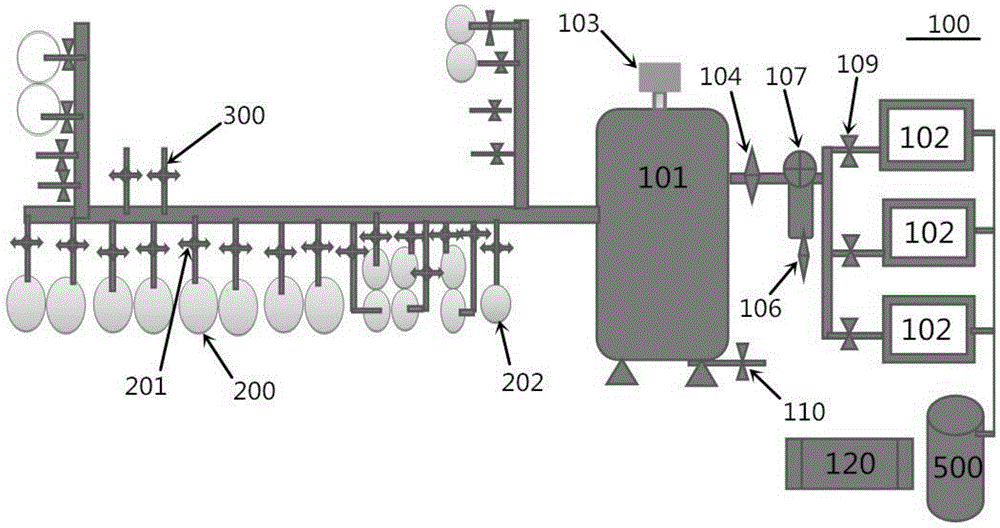
[0040] This embodiment is similar to Embodiment 1, the difference is that, as image 3 As shown, the vacuum storage cylinder 101 is externally connected to a central pipeline 400 with a larger diameter, each impregnation machine 200 is connected to the central pipeline 400 through a pipeline 401 with a smaller diameter, and each valve 201 is respectively set on each pipeline 401. In addition, the air vent 105 is arranged on the exhaust port of the liquid-gas separator 107 , and the second control valve 106 is installed on the exhaust port of the liquid-gas separator 107 . Parts not mentioned in this embodiment are the same as those in Embodiment 1, and will not be repeated here.

[0041] A control method based on the central vacuum impregnation system of the present invention comprises the following steps:

[0042] S1: Preset the upper limit and lower limit of the vacuum value in the vacuum monitor 103, so that the vacuum detector 103 when the vacuum value of the vacuum stora...


PUM


Abstract

The invention relates to the field of electrolytic solution impregnation devices, in particular to a central vacuumizing impregnation system and a control method thereof. The control method comprises a central control system and a plurality of impregnation machines, wherein the central control system comprises a vacuum air reservoir, a vacuum machine, an electric control cabinet and a vacuum monitor. The vacuum monitor is arranged on the vacuum air reservoir and can monitor air pressure of the vacuum air reservoir, the impregnation machines are communicated with the vacuum air reservoir respectively and separately through pipelines, and valves are respectively arranged on the pipelines between the impregnation machines and the vacuum air reservoir. An air pumping end of the vacuum machine is connected with the vacuum air reservoir through a pipeline, a first control valve is arranged on the pipeline between the vacuum air reservoir and the air pumping end of the vacuum machine, and the electric control cabinet is electrically and respectively connected with the first control valve, the valves and the vacuum monitor. The central vacuumizing impregnation system can prevent vacuumizing procedures of the impregnation machines from excessively depending on manual operation, production efficiency is increased effectively, and quality uniformity of volume-produced capacitor core packages is improved effectively.

Description

technical field [0001] The invention relates to the field of electrolyte impregnation equipment, in particular to a central vacuum impregnation system and a control method thereof. Background technique [0002] In the prior art, the impregnation process of capacitor core packs is usually carried out on an impregnation machine, which is generally connected to an electrolyte liquid storage tank, and the impregnation machine is generally connected to an additional vacuum machine, which is equipped with an air pump. During production, workers generally need to place the capacitor core pack in the cylinder of the impregnation machine, and then start the vacuum machine. After the air pump vacuumizes the cylinder of the impregnation machine, the electrolyte in the liquid storage tank will Due to the difference in air pressure, it automatically enters the cylinder of the impregnation machine, so that the capacitor core package in the cylinder is impregnated. However, in the product...

Claims


Application Information

Patent Timeline
IPC IPC(8): H01G13/04H01G9/00
Inventor 罗伟刘泳澎伍松廖琼
Owner ZHAOQING BERYL ELECTRONICS TECH
Why Eureka
Try Eureka