Megawatt corrugated waveguide attenuator

A corrugated waveguide and attenuator technology, which is applied in the field of megawatt-level corrugated waveguide attenuators, can solve the problems of large water load cavity, inconvenient installation and debugging, etc.

Inactive Publication Date: 2014-10-08
INST OF PLASMA PHYSICS CHINESE ACAD OF SCI
View PDF8 Cites 219 Cited by
  • Summary
  • Abstract
  • Description
  • Claims
  • Application Information

AI Technical Summary

Problems solved by technology

This results in the entire water load cavity being huge and weighing more than 100 kilograms. Such a huge s

Method used


Image

  • Megawatt corrugated waveguide attenuator
  • Megawatt corrugated waveguide attenuator
  • Megawatt corrugated waveguide attenuator

Examples


Embodiment Construction

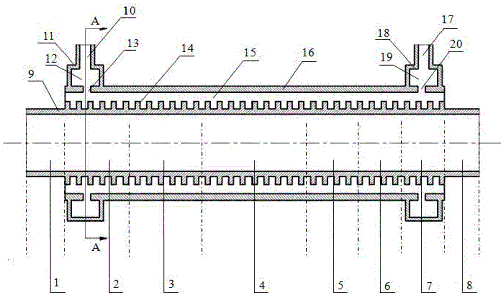
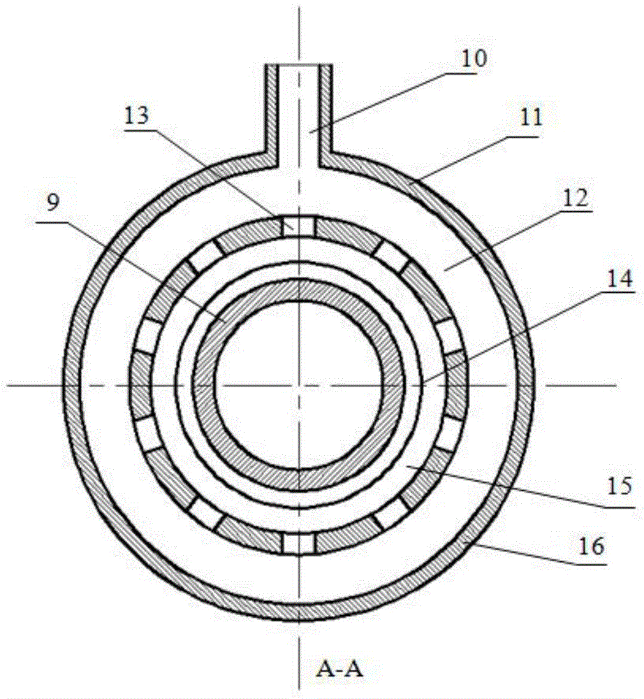
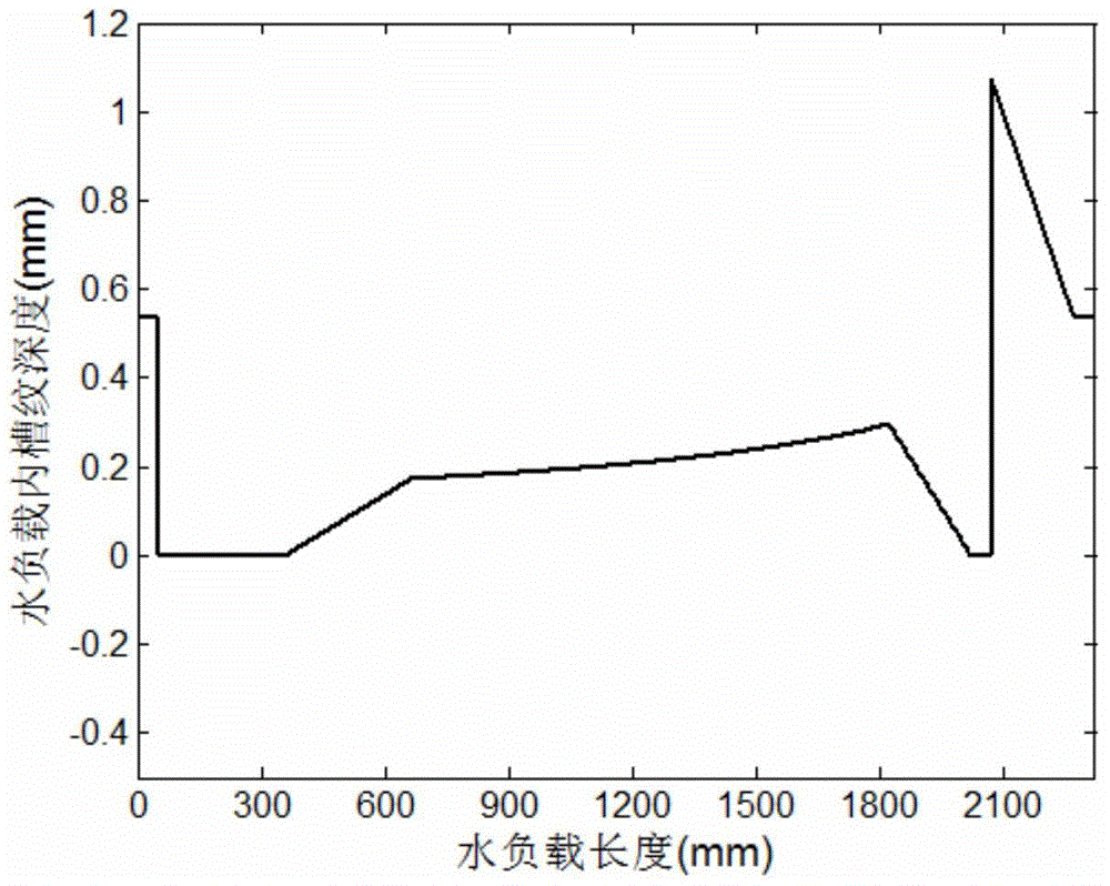
[0014] Such as figure 1 , 2 As shown, a megawatt-level corrugated waveguide attenuator includes a circular waveguide 9, on which a standard corrugated waveguide section supporting HE11 mode transmission is sequentially arranged. Smooth waveguide section 2 for mode conversion 2. Mode-changing waveguide section 3 for realizing conversion from TE11 and TM11 mixed mode to EH11 mode 3. Main attenuation waveguide section 4 for power attenuation 4. Realize conversion from EH11 mode to TE11 mode in residual power Mode-changing waveguide section 5 5, smooth waveguide section 6 for TE11 mode transmission, 6, mode-changing waveguide section 7 for realizing TE11 mode to HE11 mode conversion, and standard corrugated waveguide section 8 8 supporting HE11 mode transmission, in waveguide 9 Periodic grooves 14 are distributed on the outer wall, and a circular metal water jacket 16 is set on the periphery of the entire waveguide 13 to form a circular water channel 15. There are twelve grooves ...


PUM


Abstract

The invention discloses a megawatt corrugated waveguide attenuator. A first standard corrugated waveguide segment, a second smooth waveguide segment, a third mode changing waveguide segment, a fourth main attenuation waveguide segment, a fifth mode changing waveguide segment, a sixth smooth waveguide segment, a seventh mode changing waveguide segment and an eighth standard corrugated waveguide segment are sequentially arranged on a waveguide tube, wherein the first standard corrugated waveguide segment supports HE11 mode transmission, the second smooth waveguide segment achieves conversion from an HE11 mode to a TE11 and TM11 hybrid mode, the third mode changing waveguide segment achieves conversion from the TE11 and TM11 hybrid mode to an EH11 mode, the fourth main attenuation waveguide segment conducts attenuation on power, the fifth mode changing waveguide segment achieves conversion from the EH11 in the surplus power to a TE11 mode, the sixth smooth waveguide segment is used for TE11 mode transmission, the seventh mode changing waveguide segment achieves conversion from the TE11 mode to an HE11 mode, and the eighth standard corrugated waveguide segment supports HE11 mode transmission. According to the megawatt corrugated waveguide attenuator, the uniformity of the power attenuation magnitude per unit length inside the whole main attenuation segment can be achieved due to the design of periodic corrugations; due to the special design of waterways, the impact of high-flow-rate cooling water on waveguide walls can be reduced, and the consistency of the flow rate of the water in the whole water jacket can also be ensured.

Description

technical field [0001] The invention relates to the technical field of microwave engineering, in particular to a megawatt-level corrugated waveguide attenuator. Background technique [0002] The attenuator is a two-port device commonly used in microwave systems, and is mainly used to control the transmission power in the transmission line. The standard corrugated waveguide with an internal groove depth of about a quarter of the operating wavelength has high power capacity and extremely low transmission loss, and has become the preferred transmission device for high-power microwave systems. Electron cyclotron resonance heating system, as a typical representative of high power microwave system, is widely used in the field of nuclear fusion research. During the construction and operation of the electronic cyclone heating system, performance testing and power calibration of the gyrotron and high-power microwave transmission devices are required, and the remaining microwave ...

Claims


Application Information

Patent Timeline
IPC IPC(8): H01P1/22
Inventor 吴大俊王晓洁徐旵东刘甫坤单家方徐丽
Owner INST OF PLASMA PHYSICS CHINESE ACAD OF SCI
Why Eureka
Try Eureka