
Medium-speed coal mill with double-inlet structure

A double-entry coal pulverizer technology, applied in the field of medium-speed coal pulverizers, can solve the problems of insufficient unit variable load rate, ineffective effect, and no quantitative data support, so as to maintain uniform flow distribution, improve economic performance, Improve the effect of flow field distribution

Pending Publication Date: 2014-10-15
STATE GRID CORP OF CHINA +1
View PDF7 Cites 2 Cited by
  • Summary
  • Abstract
  • Description
  • Claims
  • Application Information

AI Technical Summary

Problems solved by technology

However, this method can only be carried out by relying on the operating experience of the technical personnel of the power plant or the design experience of the coal mill design manufacturer. As for which air ring channels are blocked, there is no accurate quantitative basis, so the transformation results are often not ideal
Even if the air ring channel that has a big problem is blocked, it is not enough to obtain an ideal uniform flow field distribution inside the medium-speed coal mill, and the effect of this transformation is very limited
Moreover, after blocking part of the air ring, due to the reduction of the flow area at the air ring, the overall pressure drop of the medium-speed coal mill will rise sharply, which will lead to a substantial increase in energy consumption, and may cause insufficient output of the coal mill and unit change. Major problems such as insufficient load rate
Therefore, the current transformation of the existing technology is firstly based on qualitative empirical analysis without quantitative data support, and secondly, the effect of this transformation itself is not obvious, which makes this type of coal mill run in an unreasonable way for a long time state, bringing economic and even security issues

Method used


Image

  • Medium-speed coal mill with double-inlet structure
  • Medium-speed coal mill with double-inlet structure
  • Medium-speed coal mill with double-inlet structure

Examples


Embodiment 1

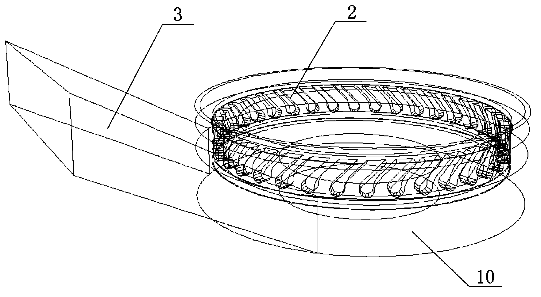
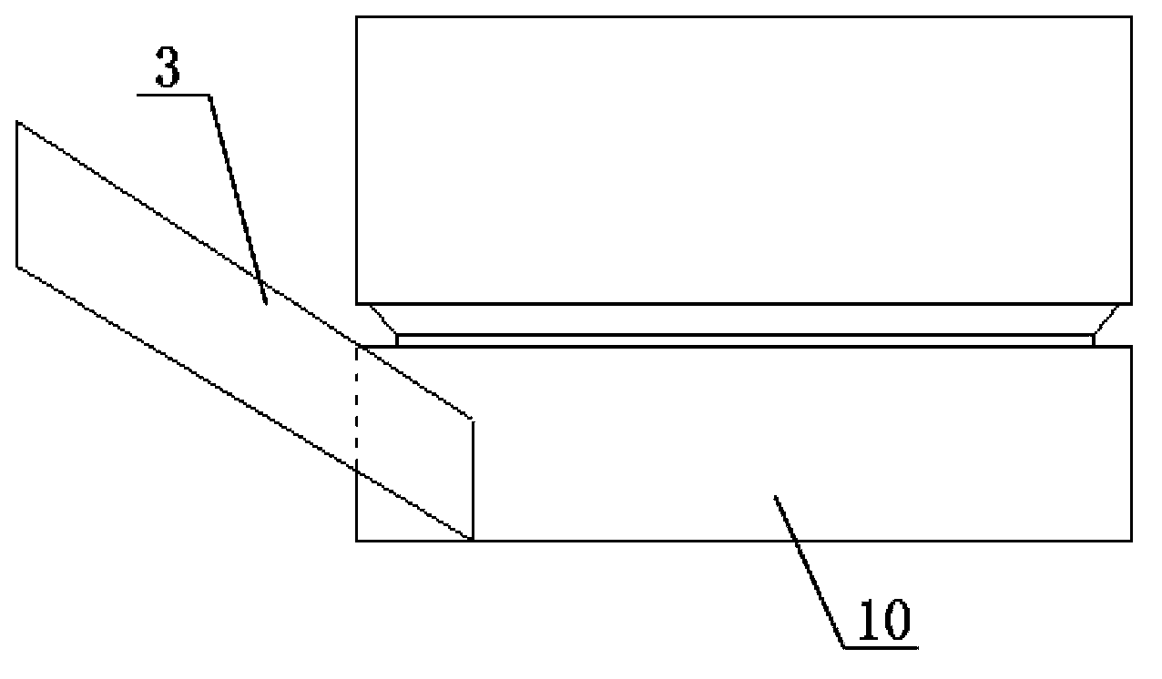
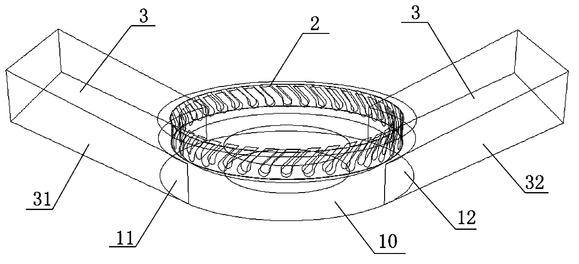
[0029] Please refer to image 3 , Figure 4 , are respectively the three-dimensional structure schematic diagram and the front view structure schematic diagram of Embodiment 1 of the medium-speed coal pulverizer with double inlet structure of the present invention. like image 3 , Figure 4 As shown, in the medium-speed coal mill with double inlet structure of the present invention, an air ring 2 is installed above the air inlet at the bottom 10 of the medium-speed coal mill, and symmetrically arranged on both sides of the bottom 10 of the medium-speed coal mill. There are air inlets 11 and 12, and the air inlets 11 and 12 communicate with the circulation space on the upper part of the medium-speed coal mill. The two air inlets 11, 12 are respectively symmetrically inserted with air inlet troughs 31, 32 having air inlet channels 3, the air inlet troughs 31 and the air inlet troughs 32 are arranged symmetrically, the air inlet troughs 31, 32 The bottom surface of the medium...

Embodiment 2

[0031] As another preferred embodiment of the present invention, please refer to Figure 5 , Image 6 , are respectively the three-dimensional structure schematic diagram and the front view structure schematic diagram of Embodiment 2 of the medium-speed coal pulverizer with double inlet structure of the present invention. In this embodiment, components that are the same as those in Embodiment 1 use the same reference numerals.

[0032] like Figure 5 , Image 6 As shown, in the medium-speed coal mill with double inlet structure of the present invention, an air ring 2 is installed above the air inlet at the bottom 10 of the medium-speed coal mill, and symmetrically arranged on both sides of the bottom 10 of the medium-speed coal mill. There are air inlets 11 and 12, and air inlet troughs 31 and 32 with air inlets 3 are inserted symmetrically on the two air inlets 11 and 12 respectively, and the air inlet troughs 31 and 32 are arranged symmetrically. Wherein, the air inlet g...


PUM


Abstract

The invention discloses a medium-speed coal mill with a double-inlet structure. An air ring is mounted above air inlets at the bottom of the medium-speed coal mill; the air inlets are symmetrically formed at the two sides of the bottom of the medium-speed coal mill respectively; air inlet groove plates with air inlet ducts are symmetrically inserted into the air inlets respectively; the bottom surface of each air inlet groove plate and the flat surface of the bottom of the medium-speed coal mill form a certain upward angle; or the bottom surface of each air inlet groove plate and the flat surface of the bottom of the medium-speed coal mill are positioned on the same horizontal plane. According to the medium-speed coal mill with the double-inlet structure, the distribution condition of flow field in the coal mill is optimized; the phenomenon of non-uniform distribution of the flow filed caused by air intake from one side is remitted or even eliminated; and the functions of reasonable discharge of pebble coal and normal stress of the coal mill are realized.

Description

technical field [0001] The invention relates to a medium-speed coal pulverizer, in particular to a medium-speed coal pulverizer with a double-inlet structure. Background technique [0002] With the increasing scale of thermal power plants and the gradual improvement of energy-saving awareness in recent years, more and more positive pressure direct-blowing pulverizing systems are equipped in my country's active and newly-built units above 300Mw, which have the advantages of rapid start-up. , flexible adjustment, small resistance, small metal wear per unit of coal grinding, compact structure, small footprint, low unit power consumption, small explosion risk and low noise. [0003] However, due to the congenital deficiencies in the design of the structure itself and the variability of the actual coal types used in power plants, the medium-speed coal mills actually put into operation in China generally suffer from insufficient output, abnormal discharge of pebble coal, rapid wear...

Claims


Application Information

Patent Timeline
IPC IPC(8): B02C23/00
Inventor 朱宪然刘成永程亮
Owner STATE GRID CORP OF CHINA
Learn More